Lithium Block™ GEN2
User Manual
Wire-Bonded Lithium-Ion Battery Module — 18650 Cell Format
Document Information
Manual Revision: K
Product Version: GEN2
Effective Date: January 2025
Classification: Customer Use
Language: English
Pages: Multi-page
Table of Contents
- 1. Introduction & Safety
- 2. Product Overview
- 3. Technical Specifications
- 4. Mechanical Design
- 5. Electrical Interface
- 6. Wire-Bond Technology
- 7. Installation Guidelines
- 8. Operating Procedures
- 9. Maintenance & Service
- 10. Troubleshooting
- 11. Safety & Compliance
- 12. Warranty & Support
- Appendix A: Connector Pinouts
- Appendix B: Revision History
1. Introduction & Safety
1.1 Welcome
Thank you for choosing the Lithium Block™ GEN2 module from EVolve Battery Systems. This manual provides comprehensive information for safe installation, operation, and maintenance of your battery module.
⚠️ Critical Safety Information
READ ALL SAFETY INFORMATION BEFORE HANDLING OR INSTALLING
- DANGER: System integrations can produce lethal voltages. Keep tools, fingers, and foreign objects away from conductive surfaces.
- WARNING: Do not operate without an appropriately configured BMS. Doing so risks catastrophic failure and voids warranty.
- Only qualified personnel should handle, install, or service these modules.
- Always use appropriate PPE including safety glasses, insulated gloves, and protective clothing.
- Never short circuit the terminals or allow conductive materials to bridge connections.
- Ensure adequate ventilation and fire suppression systems are in place.
Failure to follow safety procedures can result in serious injury, death, or property damage.
1.2 Intended Use
The Lithium Block™ GEN2 is designed for integration into battery packs for:
- Electric vehicle applications
- Energy storage systems
- Aerospace and defense platforms
- Industrial automation and robotics
- Research and development projects
- Marine and off-grid applications
1.3 Qualifications Required
- Training in lithium-ion battery safety
- Understanding of electrical systems and high-voltage safety
- Familiarity with applicable codes and standards
- Access to appropriate tools and safety equipment
2. Product Overview
2.1 Product Description
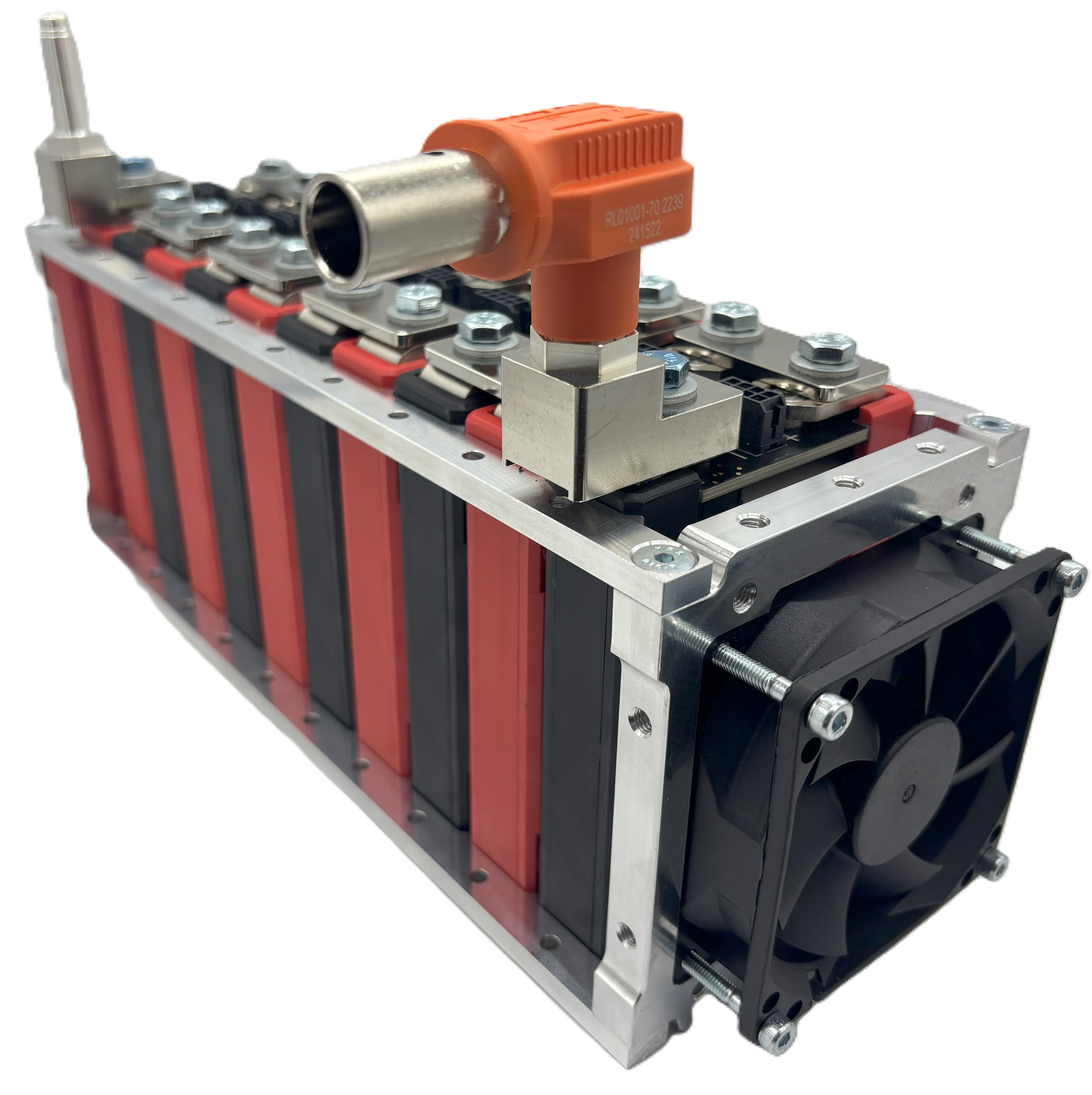
The Lithium Block™ GEN2 is a wire-bonded lithium-ion battery module engineered for reliability, scalability, and safety. Each module contains high-performance 18650 lithium-ion cells connected via ultrasonic wire-bonding technology, providing superior electrical and thermal behavior compared to traditional welded connections.
Design Philosophy
- Modular architecture for flexible scaling
- Wire-bond redundancy for enhanced safety
- Integrated monitoring and sensing
- Manufacturing-ready design
Key Advantages
- Lower thermal stress during assembly
- Graceful failure modes
- Simplified rework and service
- Consistent quality and performance
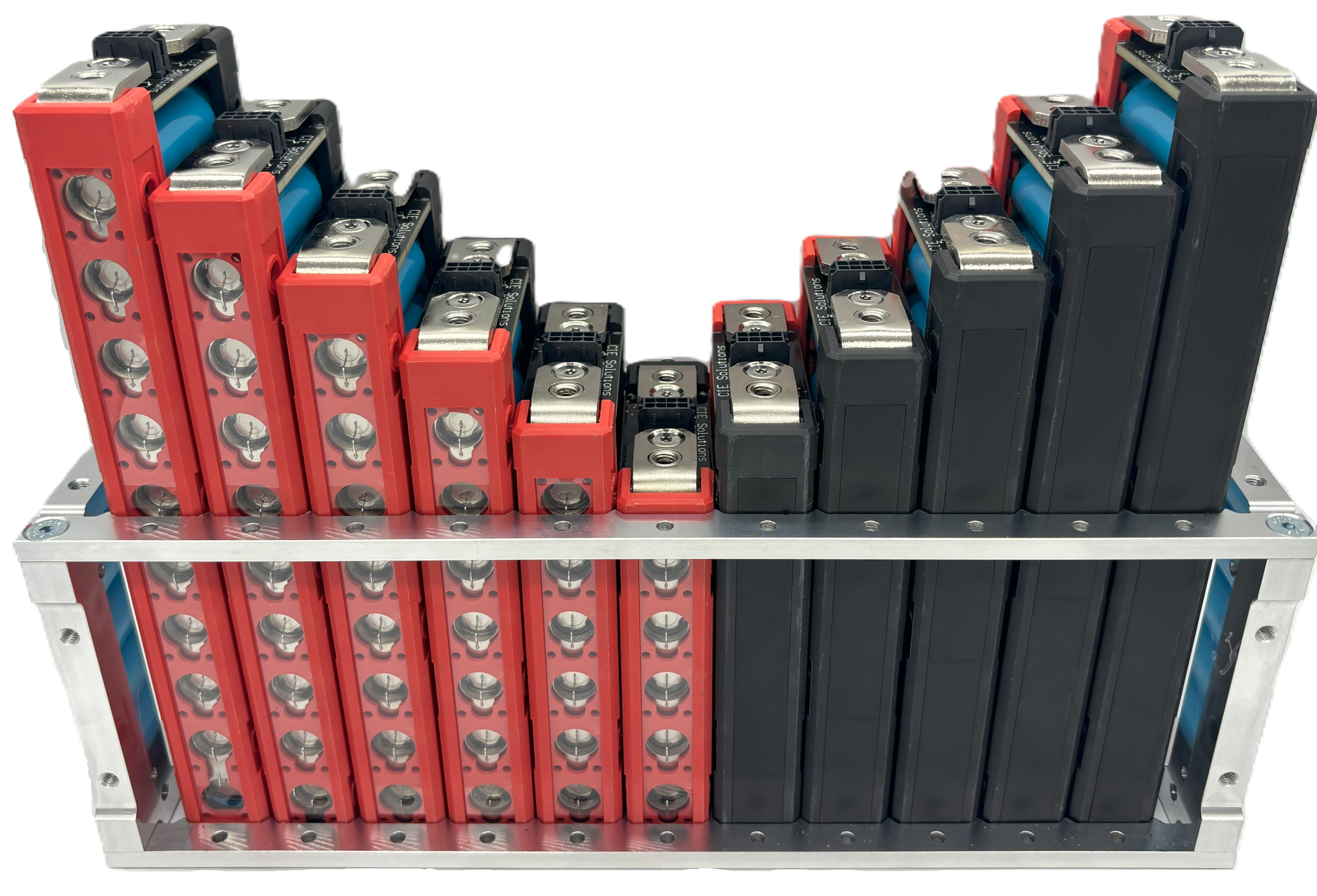
2.2 Available Configurations
The Lithium Block™ GEN2 is available in two optimized variants:
Energy Modules
Optimized for: Maximum energy density and cycle life
Applications: Long-duration discharge, energy storage, range-focused EVs
Configurations: 5P, 6P, 7P, 8P, 9P, 10P
Power Modules
Optimized for: High power output and fast charging
Applications: High-performance EVs, power tools, aerospace
Configurations: 5P, 6P, 7P, 8P, 9P, 10P
2.3 Wire-Bond Technology Overview
3. Technical Specifications
3.1 Energy Module Specifications
| Parameter | 5P Energy | 6P Energy | 7P Energy | 8P Energy | 9P Energy | 10P Energy | Units |
|---|---|---|---|---|---|---|---|
| Part Number | LBG2-05E | LBG2-06E | LBG2-07E | LBG2-08E | LBG2-09E | LBG2-10E | — |
| Energy Capacity | 63.0 | 75.6 | 88.2 | 100.8 | 113.4 | 126.0 | Wh |
| Charge Capacity | 17.5 | 21 | 24.5 | 28 | 31.5 | 35 | Ah |
| Nominal Voltage | 3.6 | 3.6 | 3.6 | 3.6 | 3.6 | 3.6 | V |
| Maximum Voltage | 4.2 | 4.2 | 4.2 | 4.2 | 4.2 | 4.2 | V |
| Minimum Voltage | 2.5 | 2.5 | 2.5 | 2.5 | 2.5 | 2.5 | V |
| Standard Charge Current | 8.5 | 10.2 | 11.9 | 13.6 | 15.3 | 17 | A |
| Maximum Charge Current | 8.5 | 10.2 | 11.9 | 13.6 | 15.3 | 17 | A |
| Maximum Discharge Current | 50 | 60 | 70 | 80 | 90 | 100 | A |
| Length (approx.) | 119 | 138 | 157 | 177 | 196 | 215 | mm |
| Mass (approx.) | 317 | 374 | 431 | 487 | 544 | 601 | g |
3.2 Power Module Specifications — Standard
Aluminum 5052-H32 collector plates. Collector ampacity limit: 210 A.
| Parameter | 5P | 6P | 7P | 8P | 9P | 10P | Units |
|---|---|---|---|---|---|---|---|
| Part Number | LBG2-05P | LBG2-06P | LBG2-07P | LBG2-08P | LBG2-09P | LBG2-10P | — |
| Energy Capacity | 50.4 | 60.5 | 70.6 | 80.6 | 90.7 | 100.8 | Wh |
| Charge Capacity | 14 | 16.8 | 19.6 | 22.4 | 25.2 | 28 | Ah |
| Nominal Voltage | 3.6 | 3.6 | 3.6 | 3.6 | 3.6 | 3.6 | V |
| Maximum Voltage | 4.2 | 4.2 | 4.2 | 4.2 | 4.2 | 4.2 | V |
| Minimum Voltage | 2.5 | 2.5 | 2.5 | 2.5 | 2.5 | 2.5 | V |
| Standard Charge Current | 14 | 16.8 | 19.6 | 22.4 | 25.2 | 28 | A |
| Maximum Charge Current | 30 | 36 | 42 | 48 | 54 | 60 | A |
| Maximum Discharge Current | 175 | 210 | 210 | 210 | 210 | 210 | A |
| Collector Plate | Aluminum 5052-H32, 0.125 in (3.18 mm), EN Plated | — | |||||
| Length (approx.) | 119 | 138 | 157 | 177 | 196 | 215 | mm |
| Mass (approx.) | 317 | 374 | 431 | 487 | 544 | 601 | g |
3.3 Power Module Specifications — Performance
C11000 copper collector plates. Collector ampacity limit: 357 A. Unlocks the full discharge capability of the Molicel P28A cell (35 A per cell).
| Parameter | 5P | 6P | 7P | 8P | 9P | 10P | Units |
|---|---|---|---|---|---|---|---|
| Part Number | LBG2-05P-CU | LBG2-06P-CU | LBG2-07P-CU | LBG2-08P-CU | LBG2-09P-CU | LBG2-10P-CU | — |
| Energy Capacity | 50.4 | 60.5 | 70.6 | 80.6 | 90.7 | 100.8 | Wh |
| Charge Capacity | 14 | 16.8 | 19.6 | 22.4 | 25.2 | 28 | Ah |
| Nominal Voltage | 3.6 | 3.6 | 3.6 | 3.6 | 3.6 | 3.6 | V |
| Maximum Voltage | 4.2 | 4.2 | 4.2 | 4.2 | 4.2 | 4.2 | V |
| Minimum Voltage | 2.5 | 2.5 | 2.5 | 2.5 | 2.5 | 2.5 | V |
| Standard Charge Current | 14 | 16.8 | 19.6 | 22.4 | 25.2 | 28 | A |
| Maximum Charge Current | 30 | 36 | 42 | 48 | 54 | 60 | A |
| Maximum Discharge Current | 175 | 210 | 245 | 280 | 315 | 350 | A |
| Collector Plate | C11000 Copper (ETP), 0.125 in (3.18 mm) | — | |||||
| Length (approx.) | 119 | 138 | 157 | 177 | 196 | 215 | mm |
| Mass (approx.) | 340 | 404 | 468 | 532 | 596 | 660 | g |
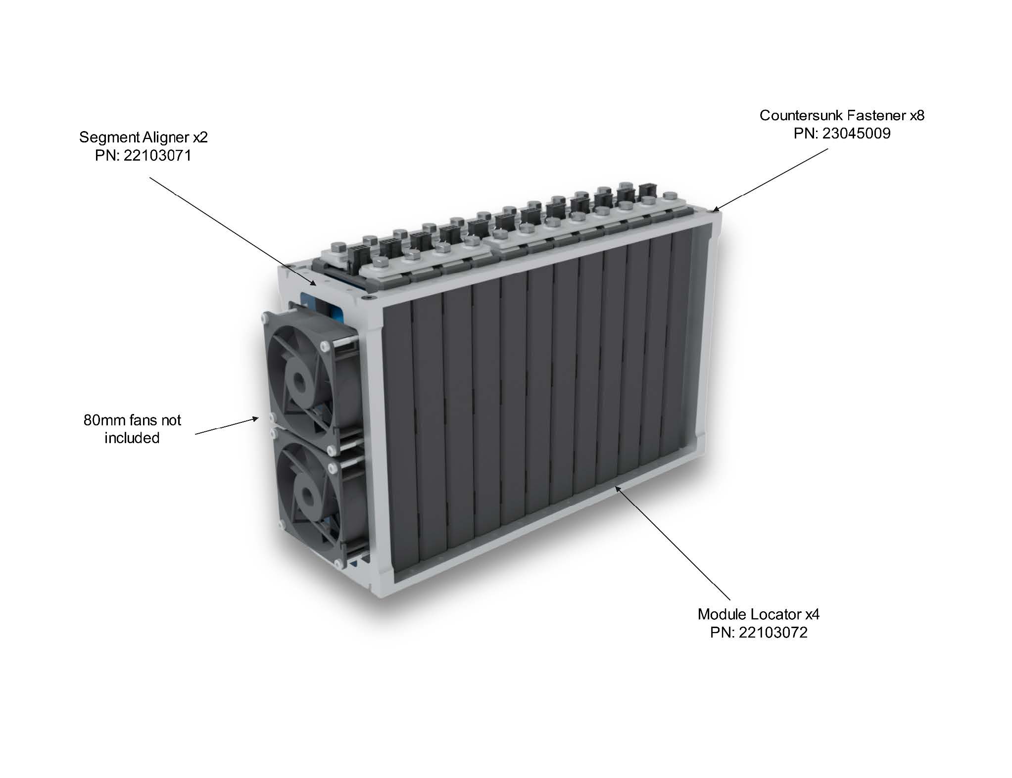
3.21 Subcomponent Identification
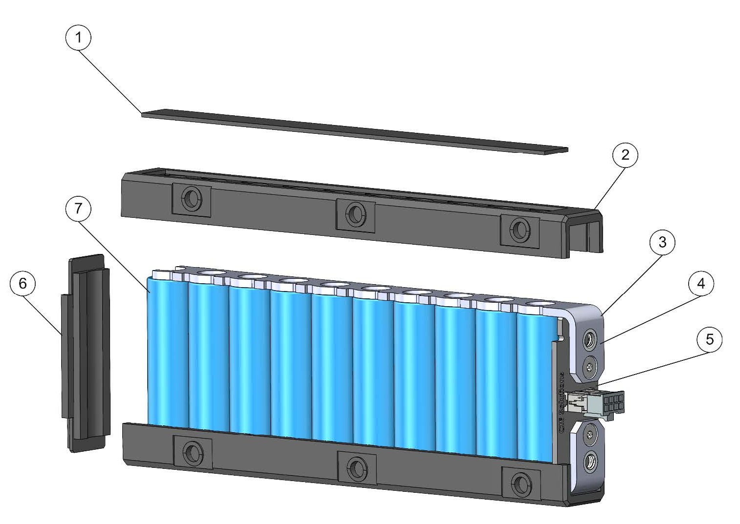
| ID | Description | PN | Qty per Module | Material |
|---|---|---|---|---|
| 1 | Black Bond Cover | 22105008 | 2 | UL94 V-0 ABS (~34 kV/mm Dielectric Strength) |
| 2 | Black Side Cover | 22105004 | 2 | UL94 V-0 ABS (~34 kV/mm Dielectric Strength) |
| 3 | Collector Plate | 22102096 (Std) / 22102097 (Perf) | 2 | Standard: EN Plated Al 5052-H32 | Performance: C11000 Cu |
| 4 | Bus Bar Mounting PEM | — | 2 | 300 Series SS |
| 5 | PCBa | 23048003 | 1 for Gen II, 0 for Gen I | FR4 PCB |
| 6 | Bottom Cover | 22105005 | 1 | UL94 V-0 ABS (~34 kV/mm Dielectric Strength) |
| 7 | Battery Cell | — | 5–10 | n/a |
3.22 General Module Information
| Item | Power Standard | Power Performance | Energy |
|---|---|---|---|
| Battery Cell PN | Molicel P28a | Molicel P28a | Molicel M35a |
| Collector Plate | Al 5052-H32 (EN Plated) | C11000 Cu (ETP) | Al 5052-H32 (EN Plated) |
| Max Collector Ampacity | 210 A | 357 A | 210 A |
| Bonding Wire | 500µm >99.997% Alu | 500µm >99.997% Alu | 300µm >99.997% Alu |
| PCB Conformal Coating | Urethane | Urethane | Urethane |
| Construction Material | UL94 V-0 ABS | UL94 V-0 ABS | UL94 V-0 ABS |
| Thermal Gap Filler | <1mm 3M DP 125 | <1mm 3M DP 125 | <1mm 3M DP 125 |
| Electrical Conductor Spacing Standard | IEC 60664 | IEC 60664 | IEC 60664 |
| PCB Standards (where applicable) | IPC Class II | IPC Class II | IPC Class II |
| Cell Jacket Material | PET | PET | PET |
| Cell Insulator Ring Material | PC | PC | PC |
| Maximum System Voltage | 500 VDC | 500 VDC | 500 VDC |
| Approximate Wire Bond Fuse Rating | 58A | 58A | 30A |
4. Mechanical Design
4.1 Understanding Your Part Number
The part number convention is as follows:
- LB = Lithium Block (present in all modules)
- G(n) = Product generation (G1 legacy without PCBs, G2 with PCBs)
- (xx) = Parallel configuration (05–10). Example: "06" for a 6P module
- (y) = Cell type designator: E for Energy, P for Power
- -CU = Optional suffix indicating Performance tier (C11000 Cu collector plates). Power modules only. Omit for Standard (Al) tier.
4.2 Physical Dimensions
Standard Envelope
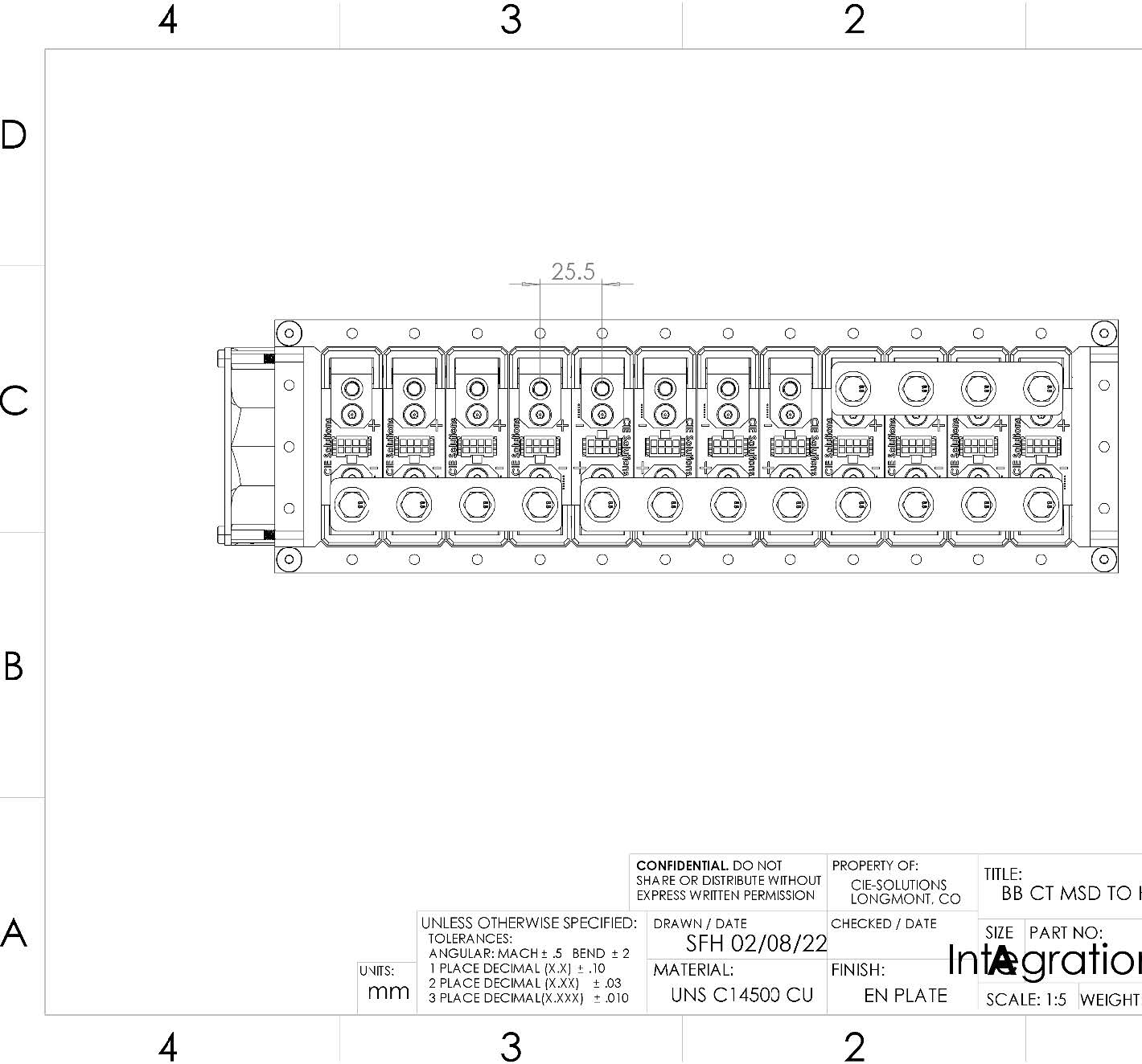
Height:80.75 mm (fixed) | Width: 25.5 mm (fixed)
Length: Variable by parallel count (see specifications)
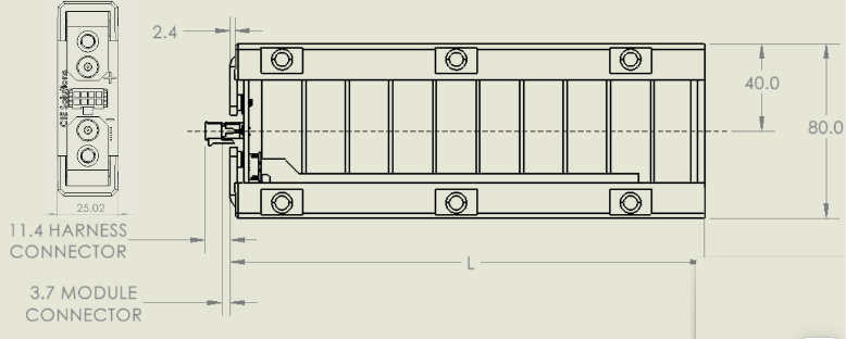
| Dimension | 5P | 6P | 7P | 8P | 9P | 10P |
|---|---|---|---|---|---|---|
| Lbody [mm] | 115.9 | 135.9 | 156.0 | 176.1 | 196.1 | 216.2 |
| Loverall [mm] | 118.4 | 138.4 | 158.5 | 178.5 | 198.6 | 218.7 |
| Ltotal [mm] | 129.7 | 149.8 | 169.9 | 189.9 | 210.0 | 230.1 |
*STEP files of each module variation can be downloaded at the EBS website.
Mounting Features
- Bus bar mounting PEMs: 300 Series SS, M6 × 1 mm thread
- Bus bar hole spacing: 25.5 mm center-to-center
- HV terminal torque: 5.5 Nm with Loctite 243 (stick, not liquid)
- Bracketing system available separately for structural retention
4.3 Enclosure Materials
| Component | Material | Properties | Standards |
|---|---|---|---|
| Main Housing | 15% glass-fiber reinforced, flame-retardant ABS (injection molded) | Dimensional stability • Low shrinkage • Good mechanical properties | Resin flammability rating: UL94 V-0 (thickness-dependent, per supplier datasheet) |
| Collector Plate (HV current collector) | Standard: Aluminum 5052-H32, 0.125 in (3.18 mm), EN Plated Performance: C11000 Copper (ETP), 0.125 in (3.18 mm) | Standard: 210 A max ampacity • Corrosion resistant Performance: 357 A max ampacity • Full P28A cell capability | Standard: Material temper H32 Performance: Power modules only |
| Bus Bar Mounting PEM | 300 Series SS | Corrosion resistant | M6 × 1 mm thread |
| Bracketing System (accessory) | See separate bracketing system manual | Endplates, compression hardware | Sold separately; own part numbers |
4.3.1 Housing Material Properties (Resin Datasheet Reference)
The enclosure resin is a 15% glass-fiber reinforced, flame-retardant ABS. The values below are typical resin datasheet properties provided for engineering reference.
| Parameter | Value | Standard / Notes |
|---|---|---|
| Physical | ||
| Density (23°C) | 1.24 g/cm³ (≈ 0.0448 lb/in³) | ISO 1183 |
| Molding Shrinkage (23°C) | 0.2–0.6 % | ISO 2577 |
| Melt Index (220°C, 10 kg) | 25 g/10 min | ISO 1133 |
| Mechanical | ||
| Tensile Strength | 50 MPa (≈ 7,252 psi) | ISO 527 (10 mm/min) |
| Elongation at Break | 3 % | ISO 527 (10 mm/min) |
| Flexural Strength | 90 MPa (≈ 13,053 psi) | ISO 178 (2.0 mm/min) |
| Flexural Modulus (E) | 3000 MPa (≈ 435,113 psi) | ISO 178 (2.0 mm/min) |
| Izod Notched Impact (23°C) | 6 kJ/m² | ISO 180 |
| Thermal | ||
| HDT | 85 °C (185 °F) @ 1.8 MPa | ISO 75 |
| Vicat Softening Temperature | 95 °C (203 °F) | ISO 306 (120°C/hr, 50N) |
| Electrical | ||
| Volume Resistivity | 1E16 Ω·cm | IEC 60093 |
| Dielectric Strength | ~34 kV/mm | IEC 60243 |
| Flammability | ||
| Flame Rating | UL94 V-0 (1.5 mm / 2.0 mm / 3.2 mm) | UL94 (resin rating; thickness-dependent) |
Notes
- Values shown are typical resin datasheet properties; molded part properties vary with fiber orientation and processing.
- "E" is elastic modulus (stiffness), not a pass/fail "withstand" rating.
- This manual does not claim temperature-dependent modulus (e.g., "E @ 60°C") unless specifically provided by the supplier or supported by part-level testing.
4.4 Thermal Design
| Component/Property | Specification |
|---|---|
| Thermistors | 10 kΩ ±0.5% NTC type |
| Thermal Gap Filler | <1mm 3M DP 125 |
5. Electrical Interface
5.1 Power Connections
High Voltage Terminals
Positive Terminal: M6 threaded stud, copper alloy
Negative Terminal: M6 threaded stud, copper alloy
Torque Specification: 5.5 Nm with Loctite 243 (stick, not liquid)
Recommended Hardware: M6 ring terminals, copper or tinned copper
5.2 Sense Harness
Monitoring Connections
Sense Harness Connector: Molex 430450812 (cell voltage & thermistors)
Temperature Sensing: Integrated NTC thermistors
Wire Gauge: 26–24 AWG
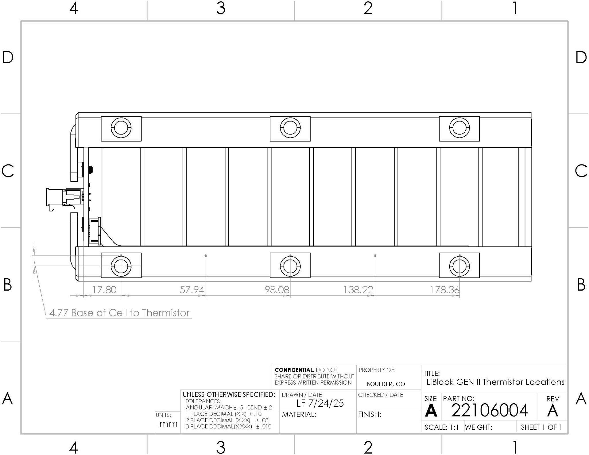
5.3 Thermistor Specifications & Locations
| Parameter | Specification | Tolerance | Notes |
|---|---|---|---|
| Resistance @ 25 °C | 10 kΩ | ±0.5% | NTC type |
| Beta Value | 3380 K | ±1% | 25 °C to 85 °C |
| Maximum Voltage | 5 V | — | Measurement circuit |
| Response Time | 5 s | — | 63% of step change |
| Operating Range | −40 °C to +125 °C | — | Sensor range |
| Quantity per Module | 5P/6P: 3; 7P/8P/9P: 4; 10P: 5 | — | |
| Placement | Adhered to 18650 cell can | — | ~4.77 mm above base; first at ~17.80 mm from PCB edge; ~40.14 mm pitch |
5.4 LV Connector (Board)
Connector Details
Board Connector: Molex 430450812 (8-position)
Mating Connector: Molex 43025-0800
Crimp Terminals: Molex 43030-0007
Wire Gauge: 26–24 AWG
See Appendix A for complete pinout diagrams and wiring instructions.
5.22 GEN2 PCB Specs
| Parameter | Specification | Notes / PN |
|---|---|---|
| Board Class | IPC Class II | Conformance & inspection |
| Creepage/Clearance | Per IEC 60664 | Conductor spacing standard |
| Thermistor Type | 10 kΩ NTC, β=3380 K | ±0.5% @25 °C |
| Max Thermistor Voltage | 5 V | — |
| Voltage Sense Fuse | PTC Resettable 200 mA | 0ZCK0020FF2G |
| LV Connector (Board) | Molex 430450812 | — |
| Mating Connector | Molex 43025-0800 | Crimp 43030-0007 |
| Bus Bar Thread Class | M6 × 1 mm | — |
| Unfused Sense Lead | <10 mm | Keep minimal length |
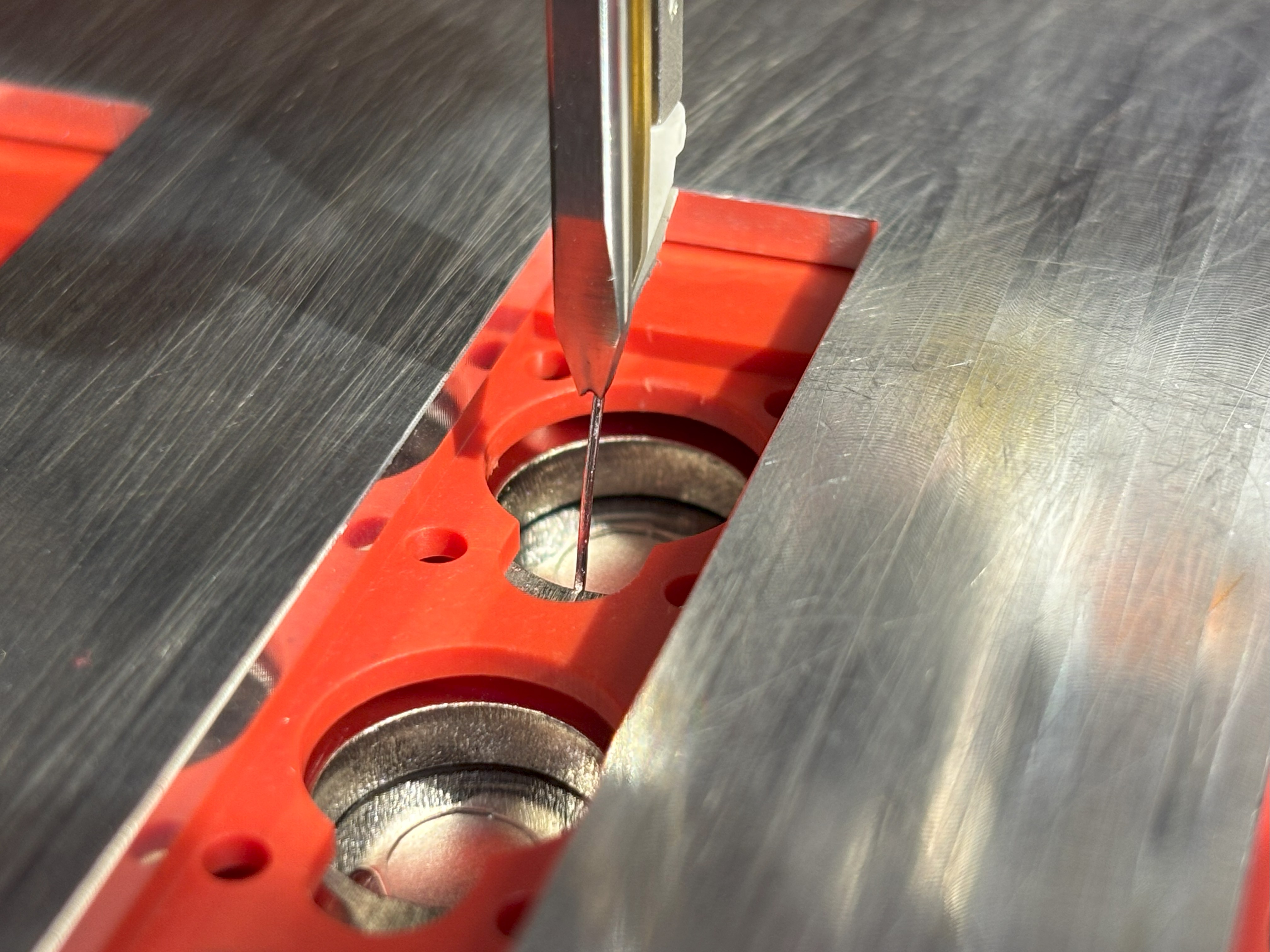
6. Wire-Bond Technology
6.1 Process Overview
EVolve Battery Systems employs ultrasonic wire-bonding to create electrical connections between lithium-ion cells. This solid-state process offers significant advantages over fusion welding methods.
How Ultrasonic Wire-Bonding Works
- Preparation: Cell terminals are cleaned and prepared for bonding
- Positioning: Aluminum wire or ribbon is positioned on the terminal
- Bonding: Ultrasonic energy creates a solid-state metallurgical bond
- Loop Formation: Wire is formed into a compliant loop
- Second Bond: Wire is bonded to the next terminal, completing the connection
6.2 Technical Advantages
Process Benefits
- No molten metal phase
- Minimal heat input to cells
- No spatter or contamination
- Highly repeatable process
- Excellent automation compatibility
Performance Benefits
- Low electrical resistance
- High mechanical compliance
- Excellent fatigue resistance
- Predictable failure modes
- Individual bond redundancy
6.3 Safety Features
Wire-Bond Fusing Characteristics
Individual wire bonds exhibit fuse-like behavior under overcurrent conditions:
- Power Modules: ~58 A per-bond (median)
- Energy Modules: ~30 A per-bond (median)
- Multiple Bonds: Current sharing provides redundancy
- Graceful Degradation: Individual bond failure doesn't cause catastrophic failure
Fuse sizing (FSAE): Per EV.6.6.5 in the FSAE rulebook, size the main pack fuse at or below ⅓ of the cumulative fusing current for the module (e.g., 58A × number of cells for Power modules).
6.4 Quality Control
- Automated pull and shear testing per MIL-STD-883
- Inline process monitoring and data logging
- Visual inspection under magnification
- Electrical continuity and resistance verification
- Statistical process control and traceability
7. Installation Guidelines
7.1 Pre-Installation Checklist
⚠️ Before You Begin
- Verify all personnel are trained and qualified
- Ensure proper PPE is available and worn
- Confirm adequate ventilation and fire suppression
- Have emergency procedures and contacts ready
- Verify tools are insulated and in good condition
- Check that work area is clean and organized
7.2 Unpacking and Inspection
- Visual Inspection: Check packaging for damage during shipping. Report any damage to carrier and EVolve Battery Systems immediately.
- Module Inspection: Examine module for physical damage, cracks, or deformation. Do not use if any damage is observed.
- Connector Check: Verify all connectors are intact and properly seated. Check for bent pins or damaged housings.
- Documentation Review: Confirm all documentation, test reports, and certificates are included with shipment.
7.3 Mechanical Installation
- Mounting Preparation: Ensure mounting surface is flat, clean, and properly grounded. Verify mounting hole alignment.
- Thermal Interface: Apply thermal interface material if using cold plates or enhanced heat dissipation.
- Module Placement: Carefully position module ensuring proper alignment with mounting holes and clearance for connections.
- Fastening: Secure bus bar connections to M6 PEM studs. Torque to 5.5 Nm with Loctite 243 (stick, not liquid). Use bracketing system (sold separately) for structural retention if required.
7.4 Electrical Installation
- Power Connections: Install ring terminals on power cables. Ensure proper crimp and insulation. Torque to 5.5 Nm with Loctite 243 (stick, not liquid).
- Sense Harness: Connect monitoring harness ensuring proper pin alignment. Verify secure connection with gentle pull test.
- Insulation Test: Perform insulation resistance test between HV terminals and chassis ground (minimum 1 MΩ at 500 V DC).
- Continuity Check: Verify electrical continuity through power path and proper sensor readings.
7.5 System Integration
BMS Integration Requirements
- Cell Monitoring: Individual cell voltage and temperature monitoring
- Balancing: Active or passive cell balancing capability
- Protection: Overvoltage, undervoltage, overcurrent, overtemperature
- Communication: CAN bus or other protocol for system integration
Pack-level fuse: Required. Max fuse rating must be less than 120% of the cumulative parallel module rating. For FSAE applications, size at ⅓ of cumulative fusing current per EV.6.6.5.
8. Operating Procedures
8.1 Initial Commissioning
- Pre-Commissioning Checks: Verify all connections, insulation resistance, and BMS configuration.
- Initial Charge: Perform initial charge cycle at reduced rate (C/10) while monitoring all parameters.
- Capacity Test: Conduct capacity verification test to confirm module performance meets specifications.
- System Validation: Test protection functions and emergency shutdown procedures.
8.2 Normal Operation
Charging Guidelines
- Use CC-CV charging profile
- Respect maximum charge current limits
- Monitor temperature during charging
- Terminate charge at 4.2 V per cell
- Allow thermal equilibration
Discharge Guidelines
- Monitor current and temperature
- Respect continuous current limits
- Implement low-voltage cutoff at 2.5 V
- Avoid deep discharge conditions
- Monitor for fault conditions
8.3 Monitoring Parameters
| Parameter | Normal Range | Warning Level | Alarm Level | Action Required |
|---|---|---|---|---|
| Cell Voltage | 2.5–4.2 V | 2.8 V / 4.15 V | 2.5 V / 4.2 V | Reduce current / Stop |
| Module Temperature | 10–45 °C | 50 °C | 60 °C | Reduce current / Stop |
| Charge Current | 0 – Std Rate | 110% Std | 120% Std | Reduce / Stop charging |
| Discharge Current | 0 – Cont Rate | 110% Cont | 120% Cont | Reduce / Stop discharge |
| Voltage Imbalance | < 50 mV | 100 mV | 200 mV | Balance / Service |
8.4 Emergency Procedures
🚨 Emergency Response
Thermal Runaway Signs
- Rapid temperature rise
- Visible smoke or vapor
- Unusual odors
- Swelling or deformation
- Sparking or arcing
Immediate Actions
- Disconnect power immediately
- Evacuate personnel from area
- Activate fire suppression if available
- Contact emergency services
- Notify EVolve Battery Systems
9. Maintenance & Service
9.1 Routine Maintenance
Recommended Maintenance Schedule
| Interval | Maintenance Task | Personnel Required |
|---|---|---|
| Weekly | Visual inspection, parameter logging | Operator |
| Monthly | Connection torque check, cleaning | Technician |
| Quarterly | Capacity test, insulation test | Qualified Technician |
| Annually | Complete system inspection, documentation update | Engineer |
9.2 Inspection Procedures
- Visual Inspection: Check for physical damage, corrosion, loose connections, or signs of overheating. Document any anomalies.
- Electrical Testing: Measure insulation resistance, connection resistance, and verify sensor functionality.
- Performance Testing: Conduct capacity and internal resistance measurements to assess module health.
- Documentation: Record all measurements and observations in maintenance log. Compare to baseline values.
9.3 Cleaning Procedures
Approved Cleaning Methods
Exterior Surfaces: Use dry cloth or slightly damp cloth with isopropyl alcohol (70% max)
Terminals: Use contact cleaner and fine abrasive pad if necessary
Connectors: Use compressed air and contact cleaner. Ensure completely dry before reconnection
NEVER use water, solvents, or aggressive chemicals. Always disconnect power before cleaning.
9.4 Storage Guidelines
Short-Term Storage (< 6 months)
- Store at 30–50% state of charge
- Temperature: 15–25 °C preferred
- Humidity: <60% RH
- Check voltage monthly
Long-Term Storage (> 6 months)
- Store at ~40% state of charge
- Temperature: 15–20 °C preferred
- Check and recharge every 6 months
- Maintain detailed storage log
10. Troubleshooting
10.1 Common Issues and Solutions
| Symptom | Possible Cause | Recommended Action | Contact Support |
|---|---|---|---|
| Low capacity | Cell aging, temperature, imbalance | Check temperature, balance cells | If <80% rated capacity |
| High temperature | Overcurrent, poor cooling, fault | Reduce current, check cooling | If >60 °C sustained |
| Voltage imbalance | Cell mismatch, BMS issue | Check BMS balancing function | If >200 mV difference |
| High resistance | Connection issue, aging | Check connections, clean terminals | If >2× initial value |
| Sensor error | Connector issue, wire damage | Check harness connections | If persistent errors |
10.2 Diagnostic Procedures
Basic Diagnostic Tests
- Voltage Measurement: Measure individual cell voltages and module voltage
- Temperature Check: Verify thermistor readings across all sensors
- Insulation Test: Measure insulation resistance to ground (>1 MΩ required)
- Connection Resistance: Measure resistance across power connections
- Capacity Test: Perform controlled discharge to measure actual capacity
10.3 When to Contact Support
⚠️ Contact EVolve Battery Systems Immediately If:
- Any signs of thermal runaway or overheating
- Physical damage to module housing or terminals
- Capacity drops below 80% of rated value
- Persistent voltage imbalances >200 mV
- Unusual odors, smoke, or visible damage
- Any safety-related concerns
Emergency Contact: (720) 414-5502 | Email: [email protected]
11. Safety & Compliance
11.1 Safety Standards
The Lithium Block™ GEN2 is designed to support compliance with relevant safety standards:
| Standard | Application | Compliance Level | Notes |
|---|---|---|---|
| UN 38.3 | Transport safety | Module level | Test report available |
| IEC 62133 | Cell safety | Cell level | Cell manufacturer cert |
| UL 1973 | Stationary storage | System level | Pack integration required |
| IEC 62619 | Industrial batteries | System level | Pack integration required |
| ISO 12405 | EV applications | System level | Vehicle integration required |
11.2 Material Compliance
Environmental Compliance
- RoHS: Compliant with EU RoHS directive
- REACH: No substances of very high concern (SVHC)
- Conflict Minerals: Responsible sourcing practices
- Recycling: Materials selected for end-of-life recycling
11.3 Safety Architecture
Multi-Layer Safety Design
Cell Level
- Current Interrupt Device (CID)
- Pressure relief vent
- Thermal shutdown
- Internal safety circuits
Module Level
- Wire-bond fusing behavior
- Temperature monitoring
- Mechanical strain relief
- Flame-retardant housing resin (UL94 V-0 per supplier datasheet; thickness-dependent)
System Level
- BMS protection
- Pack-level fusing
- Isolation monitoring
- Emergency shutdown
11.4 Hazard Analysis
| Hazard | Risk Level | Mitigation | Detection Method |
|---|---|---|---|
| Thermal runaway | High | Temperature monitoring, current limiting | Temperature sensors, BMS |
| Overcharge | High | Voltage monitoring, charge control | Cell voltage monitoring |
| Overdischarge | Medium | Low voltage cutoff | Cell voltage monitoring |
| Overcurrent | Medium | Current limiting, fusing | Current sensors, wire-bond fusing |
| Short circuit | High | Fusing, isolation | Current sensors, voltage monitoring |
| Mechanical damage | Medium | Proper handling, mounting | Visual inspection |
12. Warranty & Support
12.1 Limited Warranty
Warranty Coverage
EVolve Battery Systems warrants the Lithium Block™ GEN2 modules to be free from defects in materials and workmanship under normal use for a period of 12 months from the date of shipment.
Covered Items
- Manufacturing defects
- Material failures
- Wire-bond integrity
- Connector defects
- Enclosure issues
Exclusions
- Misuse or abuse
- Operation outside specifications
- Unauthorized modifications
- Normal wear and aging
- Damage during shipping
12.2 Technical Support
Support Services Available
- Technical Consultation: Application engineering support
- Integration Assistance: BMS selection and configuration guidance
- Troubleshooting Support: Remote and on-site diagnostic assistance
- Training Services: Safety and operation training programs
- Documentation: Additional technical documentation and updates
12.3 Return Material Authorization (RMA)
- Contact Support: Call (720) 414-5502 or email [email protected] with issue details and module serial number.
- RMA Number: Obtain RMA number and return instructions. Do not return any product without prior authorization.
- Packaging: Use original packaging if available, or equivalent protection. Follow all hazmat shipping requirements.
- Documentation: Include RMA number, description of issue, and any relevant test data or logs.
Appendix A: Connector Pinouts
A.1 LV Connector (Board)
Molex MicroBlade / Micro JST Footprint
Board Connector: Molex 430450812 (8-position)
Mating Connector: Molex 43025-0800
Crimp Terminals: Molex 43030-0007
Wire Gauge: 26–24 AWG
| Pin | Signal Name | Description | Wire Color | Voltage Range |
|---|---|---|---|---|
| 1 | VSENSE+ | Voltage Sense + | Red | 2.5–4.2 V |
| 2 | THERM_5 | Thermistor 5 | Yellow | 0–5 V |
| 3 | THERM_4 | Thermistor 4 | Orange | 0–5 V |
| 4 | THERM_3 | Thermistor 3 | Green | 0–5 V |
| 5 | VSENSE− | Voltage Sense − | Black | 0 V (ref) |
| 6 | COM | Common return | Blue | 0 V |
| 7 | THERM_1 | Thermistor 1 | White | 0–5 V |
| 8 | THERM_2 | Thermistor 2 | Brown | 0–5 V |
A.2 Temperature Sensor Characteristics
NTC Thermistor Specifications
Type: 10 kΩ NTC, β = 3380 K
Accuracy: ±0.5% at 25 °C
Temperature Calculation:
          T(K) = 1 / (1/T₀ + (1/β) × ln(R/R₀))

          where T₀ = 298.15 K, R₀ = 10 kΩ, β = 3380 K
Appendix B: Revision History
| Revision | Date | Changes | Approved By |
|---|---|---|---|
| A | March 2020 | Initial release for GEN2 modules | Engineering |
| B | August 2020 | Updated specifications, added power modules | Engineering |
| C | January 2021 | Revised safety procedures, updated connector info | Engineering |
| D | June 2021 | Added troubleshooting section, updated warranty | Engineering |
| E | November 2021 | Updated wire-bond specifications, added maintenance schedule | Engineering |
| F | April 2022 | Revised environmental specifications, updated pinouts | Engineering |
| G | September 2022 | Added diagnostic procedures, updated safety warnings | Engineering |
| H | March 2023 | Updated compliance information, revised installation procedures | Engineering |
| I | August 2023 | Added storage guidelines, updated support contact information | Engineering |
| J | January 2025 | Complete manual restructure, updated branding, enhanced safety sections | Engineering |
| K | April 2026 | Corrected LV connector pinout table (Appendix A) to match GEN2 PCB layout | Engineering |
Document Control
Document Owner: EVolve Battery Systems Engineering Department
Review Cycle: Annual or as needed for product changes
Distribution: Customer-facing document, available on request
Language: English (primary); translations available upon request