MonoLith™
Custom Lithium-Ion Battery System
Modular high-voltage battery architecture. Bring the vehicle up in parallel. Pilot integration in weeks, not months. Certify your production pack on your timeline.
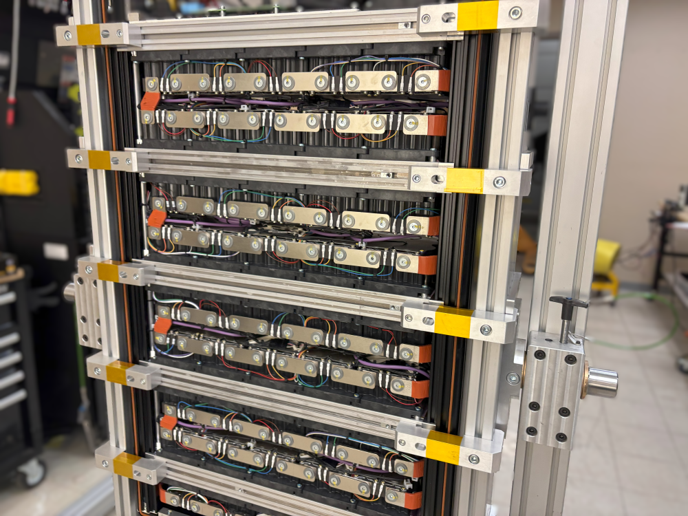
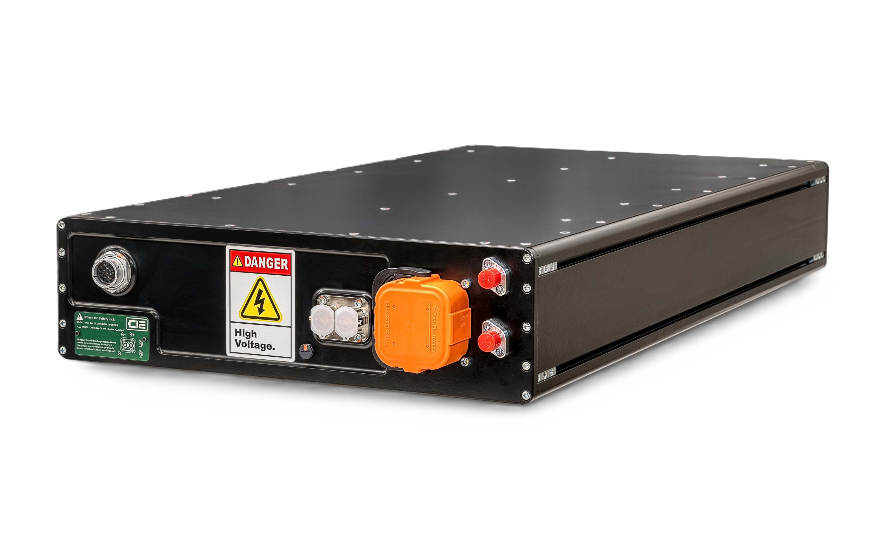
MonoLith™ Pack: Full Assembly
Structural cooling manifold, distributed BMS topology, and documented interfaces for rapid integration.
- • Documented mounting & electrical interfaces
- • Cells UN 38.3 certified; pack-level programs customer-elected
- • CAN 2.0B / J1939 (11/29-bit); DBC provided; VCU-compatible.
Revolutionary Technology Platform
Our patent-pending MonoLith™ platform represents a fundamental breakthrough in battery system architecture, delivering unprecedented scalability and cost efficiency for mission-critical applications.
Industry-First Patent-Pending Technology
Revolutionary modular architecture with proprietary scaling algorithms and thermal management systems.
Rapid Scalability Platform
Scale by 24-cell building blocks to the program's target energy. No redesign, no retooling, minimal lead time impact.
Minimal Tooling Investment
Standardized interfaces eliminate custom tooling costs. One platform serves multiple applications.
Accelerated Time-to-Market
Pre-validated modules and documented interfaces reduce integration time from months to weeks.
Who MonoLith™ Is For
MonoLith™ is designed for teams building repeatable products and platforms, not one-off personal projects.
Good Fit
- Commercial & OEM programs: emerging manufacturers, fleet operators, defense and robotics integrators, and advanced R&D teams
- Low-to-medium volume production: we specialize in OEM programs where you're building a repeatable product or vehicle platform, even starting with prototypes
- Path to multiple builds: that may start with a handful of prototypes and pilot units, but there's a clear plan for repeatable production
- Smaller than the giants: unlike large pack integrators who often won't engage until you're at very high volumes and large NRE budgets, we're willing to support smaller OEM programs and early-stage platforms
Not a Good Fit
- One-off personal projects: single custom cars, boats, or DIY machines where our engineering process and pricing don't make economic sense
- Hobby builds: purely personal projects without a path to repeatable production
- Consumer drop-in replacements: we're not a source for marine or RV battery upgrades; consumer and marine-oriented battery solutions are better suited for those applications
- No production plan: projects without a clear path from prototype to repeatable builds
Bottom line: MonoLith™ is for commercial and OEM programs building repeatable products or platforms. If you're building a real product or fleet, even at modest volumes, we're here to help.
Request a QuoteCustomer Success Stories
Real-world deployments demonstrating MonoLith™ platform advantages across industries.

Aerospace Prototype Program
Challenge
Rapid iteration required for flight test vehicle with changing power requirements
Solution
MonoLith™ modular scaling allowed rapid iterations using same base modules
Results
- 3-month development timeline
- 225% cost savings vs custom approach
- Successful flight test program
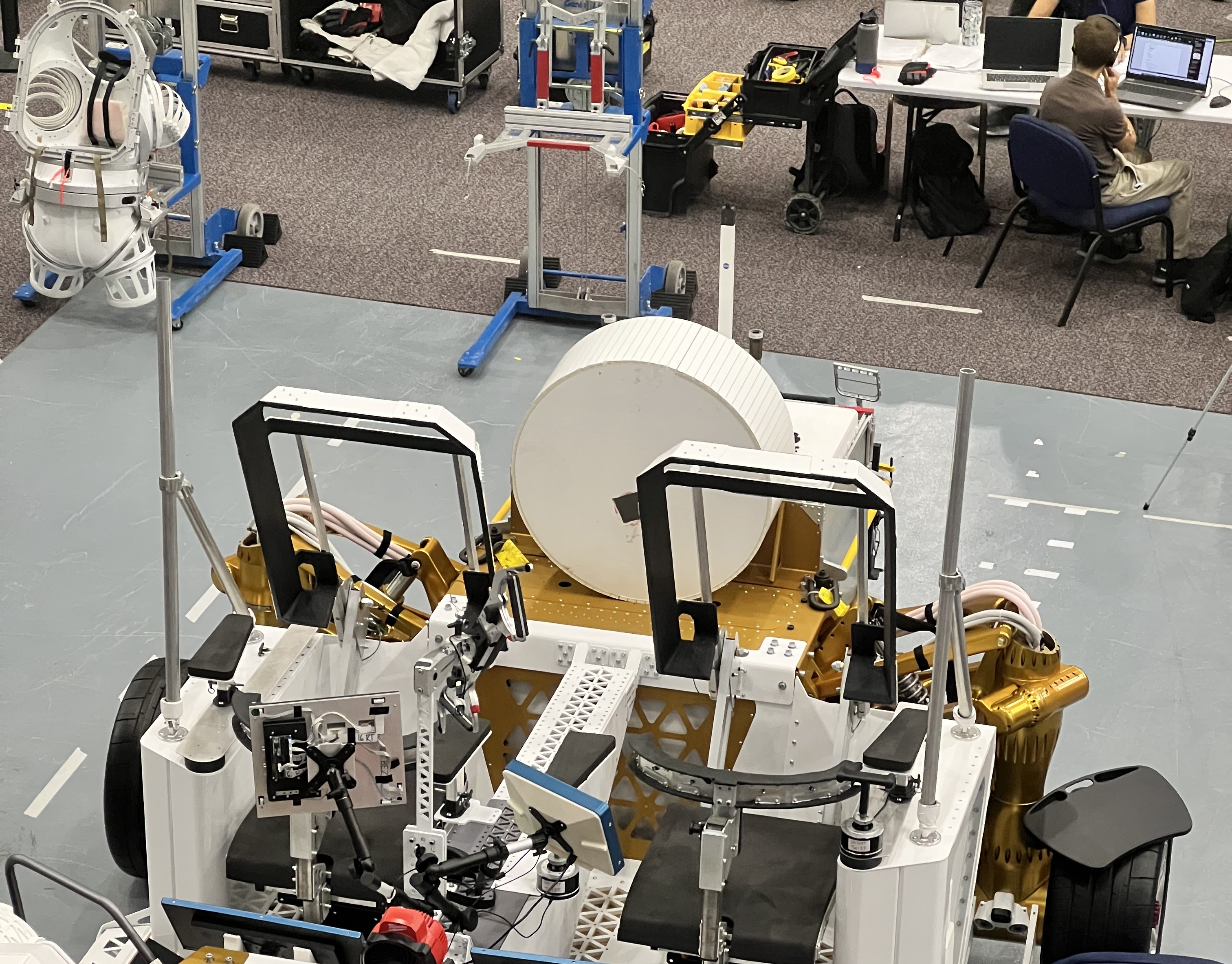
Rover Battery System
Challenge
U.S. government space agency needed a prototype battery system for terrestrial rover testing with extreme environment requirements
Solution
Dual-pack MonoLith™ modular architecture with full interface documentation — CAN, RS-485, EtherCAT, ICD, and CAD delivered with hardware
Results
- 20 kWh system delivered in 4 months
- 4× continuous discharge vs minimum requirement
- 2.25× pulse discharge vs minimum requirement
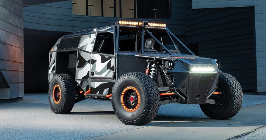
Defense Vehicle Program
Challenge
Mission-critical application requiring rapid deployment and field serviceability
Solution
MonoLith™ pack platform with comprehensive diagnostics and documented integration procedures
Results
- Faster bring-up with documented install & test
- Zero mission failures
- Exceeded MIL-STD requirements
MonoLith™ by Application
MonoLith™ powers programs across aerospace, defense, marine, robotics, and industrial applications. See application-specific guidance for each domain.
MonoLith™ in Action
Discover real-world applications and performance
The Cell at the Core
Every MonoLith pack is built around a single cell chemistry we've validated across hundreds of test hours. The pack engineering — collector plates, thermal architecture, wire bonding — is where EVolve adds value. The cell is the foundation we chose carefully, not the product we sell.
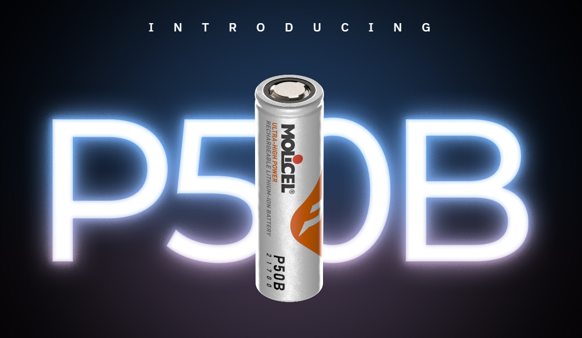
The cell inside every MonoLith pack. A 21700-format power cell chosen for its balance of energy density, discharge capability, and cycle life.
Why This Cell
Silicon-carbon composite anode
The anode formulation is what doubled cycle life from 700 to 1,400 cycles at the cell level. Silicon-carbon composites accommodate more lithium per unit volume than conventional graphite, but managing the volume expansion during cycling is the engineering challenge — and the reason the cycle life gain is real.
High-nickel layered oxide cathode
Higher nickel content pushes energy density and power delivery. The trade-off is thermal sensitivity at high states of charge, which is exactly what the thermal charts on this page quantify.
Low-temperature electrolyte formulation
The electrolyte is formulated to maintain ionic conductivity at low ambient temperatures, extending the usable charge window below 0 °C.
Cycle Life
At 23 °C, cell level, with +1C charge and −100 W discharge. A packed module runs hotter, so real-world cycle life is lower. We model pack-level degradation against your duty cycle and cooling design — the number above is a best-case anchor, not a field prediction.
Peak Power (10 s)
Per cell, 10-second pulse. Pack power scales with cell count. These are manufacturer reference figures — actual sustained output depends on thermal management, which is what the next section explores.
This cell is used in hyper EVs, racing programs, eVTOL, and heavy-lift drone applications. Molicel cells power the McMurtry Spéirling, which holds the Goodwood Festival of Speed hill climb record — a legitimate halo for the cell we build around, and a data point on what the chemistry is capable of in the right hands.
Why a Single "Continuous Power" Rating Is the Wrong Question
A vehicle doesn't draw constant peak power. Load profile and thermal management determine what a pack actually delivers. These three stories show why — using measured test data and engineering models from our Molicel INR-21700-P50B cell testing.
Discharge Rate Changes What You Get
At low rates the cell delivers full capacity. At high rates it heats up, hits its 80°C limit partway through, and terminates early with less than half its capacity delivered. There is no single "continuous" number — there's a curve.
Copper Collector Plates: When They Matter
At low current, aluminium and copper both run cool — copper is overkill. As current rises, aluminium heat-soaks quickly while copper stays flat. At high current aluminium exceeds its limit and copper doesn't.
Real Duty Cycles vs. Constant-Load Rating
A simulated vehicle drive cycle (hard acceleration, cruising, regen, stops) against the same pack held at constant peak power. The drive cycle stabilises comfortably; the constant load exceeds the cell limit in minutes. Same pack, same cooling.
The right question isn't "what's the continuous rating?"
It's "what does my application actually draw, and how does the pack handle that?"
Request a Thermal AssessmentStructural & Tunable Thermal System
Leak certified, uniform ΔT, repeatable power, and easily fluid purge/bleed.
Structural
Stiffness + protection
Tunable
Per-array flow
Uniform ΔT
Repeatable power
Fast purge/bleed
Quick fluid maintenance
Leak Certified
24h N₂ hold
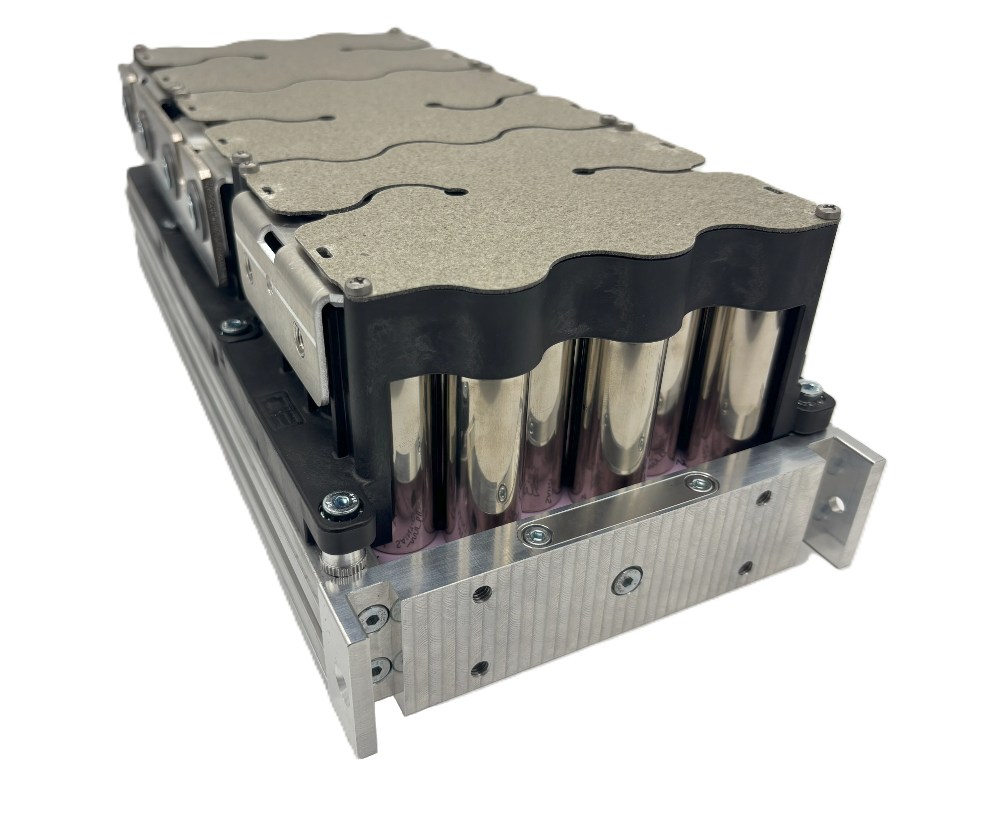
Structural, Tunable Cooling Array
Leak certified, uniform ΔT across arrays yields repeatable power and better cell life. Flow paths can be regulated as capacity scales.
The manifold adds stiffness and protects flow passages from handling shock. Per-array flow control maintains tight ΔT as arrays increase, and a thermal pad plus torque pattern ensures full-area interface. The layout is designed for rapid purge and bleed, and each manifold is pressure-held with dry nitrogen for 24 hours with pressure-decay logged to the serial number.
Liquid Cooling, Proven on Hardware
Four modules in one pack. Same cells, same current, same instant. Two had the conductive pad removed — a 2 mm air gap to the cold plate. Two were actively liquid-cooled. The temperature difference between them is the cooling system's effect and nothing else.
| Test | Pack Current | Load Duration | Uncooled Peak | Cooled Peak | Benefit | Uncooled Hit Limit |
|---|---|---|---|---|---|---|
| CH1 | 180 A | 28.9 min | 47°C | 36°C | 11 K | No |
| CH2 | 360 A | 10.1 min | 52°C | 43°C | 9 K | Yes |
The 360 A run is the one that matters
The uncooled modules reached the 53°C test limit and the run ended. The cooled modules sat at 43°C with 10 K of headroom. Cooling didn't just lower a number — it was the difference between finishing the run and stopping.
What this test is — and isn't
A physical test on a real four-module pack. Peak temperatures are measured from the test report; curve shape between start and peak is reconstructed from published figures. The 53°C line is a test limit, not a cell limit — the cells tolerate considerably more. This shows cooling works and by how much at these currents; it does not establish maximum heat rejection.
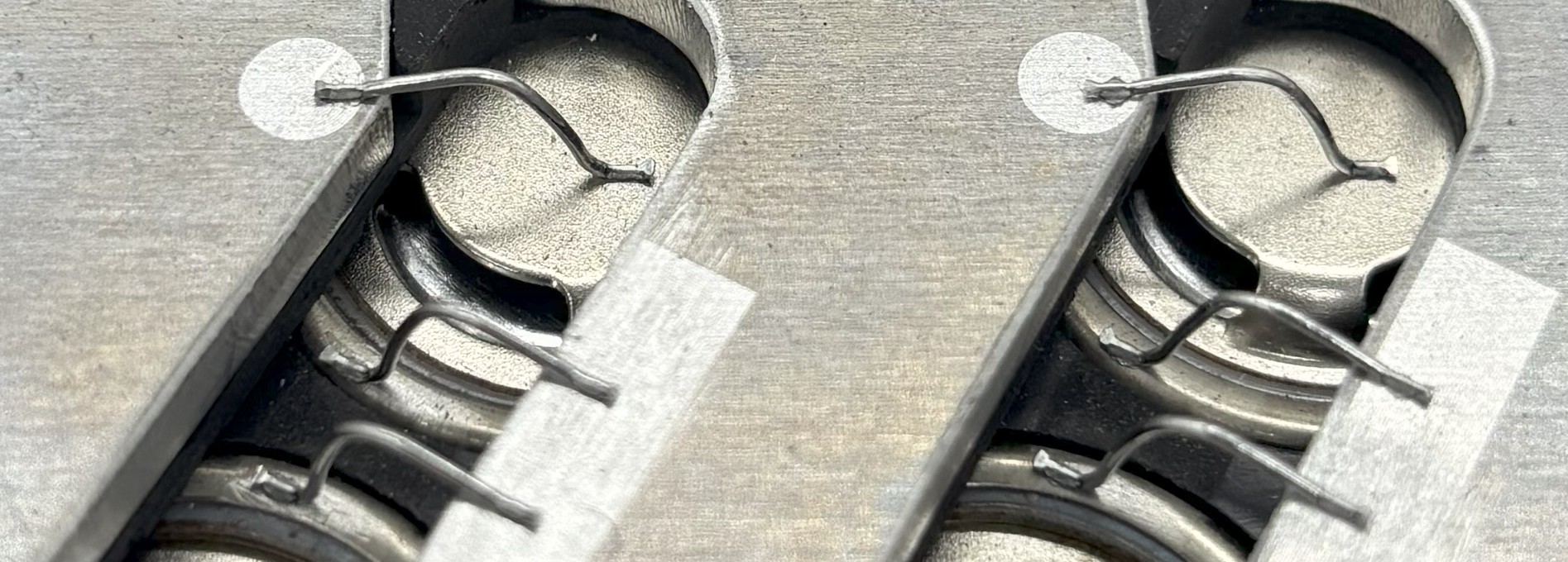
Wire-Bonding in MonoLith™
Understand where wire-bonding fits in the pack, and when we combine it with other joining methods.
- Decoupled development with low-heat interconnects
- Diagnostics to cell/board level; clean rework paths
- Hybrid strategy: wire-bond + laser where seams make sense
| Heat into cell | Low |
| Failure behavior | Redundant / compliant |
| Reworkability | High (bond-level) |
| QC methods | Pull/Shear + inline logs |
Your ROI, Quantified
Tune a few assumptions and see the economics shift in real time.
ROI / Total Cost of Ownership
Browse the Full Pack Catalog
Configurations spanning 28.8V–856.8V nominal; 1,000 Vdc system maximum. 5–62.2 kWh per pack, and 7–446 kW. Filter by voltage, energy, or power band.
View Pack CatalogTechnical Specifications
Comprehensive technical data for engineering teams and system integrators.
Power & Energy
Physical & Environmental
Safety & Control
Controls & Communications
The BMS publishes limits & health on CAN and supervises precharge and contactors. Your VCU (provided by you) commands the loads within published limits. The BMS CAN messages are configurable to match your VCU. DBC is provided; message map & rates are documented in the DBC and interface documentation.
Integration highlights
- • CAN 2.0B / J1939 (11/29-bit), up to 1 Mb/s
- • DBC provided for telemetry, limits, faults
- • VCU-compatible: BMS enforces safety, opens on fault; VCU provided by customer
- • Configurable IDs/rates (documented ranges in DBC and interface documentation)
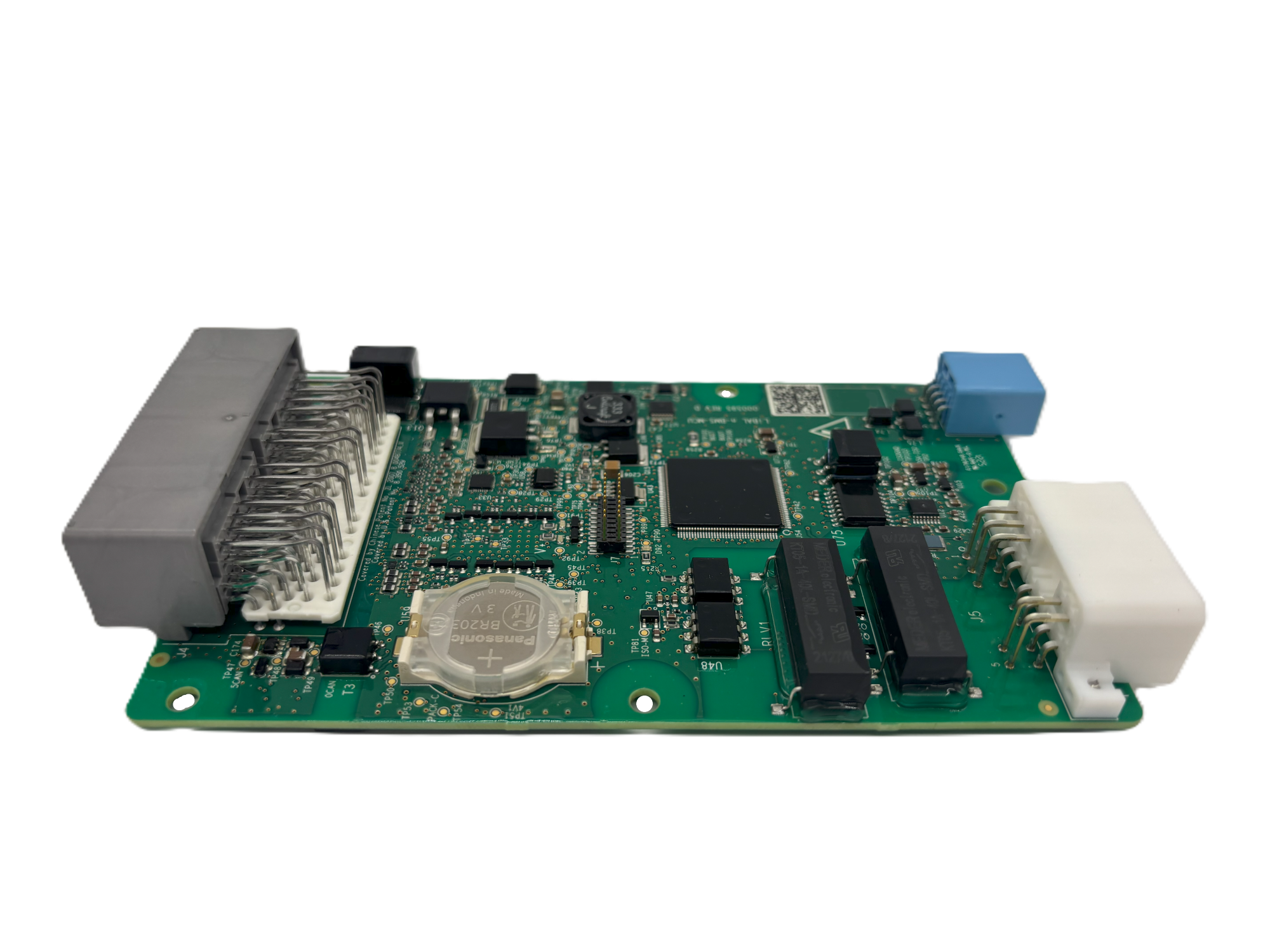
Engineering example (CAN 2.0B / J1939)
IDs shown as examples. Your DBC carries the actual IDs and scaling.
# IDs shown as examples. Your DBC carries the actual IDs, scaling, and endianness.

0x18FF50E5  BMS_Limits        (100 ms) I_Charge_Max (A), I_Discharge_Max (A), V_Charge_Max (V), Flags
0x18FF51E5  BMS_Status        (100 ms) Pack_V (0.1V), Pack_I (0.1A), SoC (%), Contactor_State, Precharge_State

# ---- Cell / Balance telemetry ----
0x18FF60E5  VCU_Command       (100 ms) Enable_Charge, Enable_Discharge, Charger_Ireq (A), Charger_Vreq (V)
0x18FF61E5  Cell_V_Page0      (100 ms) V0..V7 (mV)               # 8 cells per page

# ---- Protection / isolation ----
0x18FF70E5  Isolation_Status  (100 ms) Riso_Pos (kΩ), Riso_Neg (kΩ), ISO_Warn, ISO_Fault
0x18FF71E5  Faults_Latched    (100 ms) Fault_Bitmap0, Fault_Bitmap1, Warn_Bitmap0, Warn_Bitmap1

# ---- Contactor / precharge detail ----
0x18FF78E5  Precharge_Detail  (100 ms) PC_State, PC_Timer (ms), V_Bus (0.1V), V_Pack (0.1V), dV (V), Inrush_Est (A)
0x18FF79E5  Contactors_Detail (100 ms) Main_Pos, Main_Neg, Precharge, Weld_Detect

0x18FF72E5  Interlock_Status  (100 ms) HVIL_Loop_State (reported status only)
0x18FF7AE5  Logger_Summary    (500 ms) Max_Today_T (°C), Min_Today_V (mV), Trip_Count, Uptime (s)
0x18FF7BE5  Event_Trace       (on evt) Event_ID, Severity, Arg0, Arg1

# Cell voltage telemetry is delivered on a rotating page index within the available frame budget.
# Full-pack cell voltage refresh therefore takes multiple broadcast cycles; the refresh interval
# for your series count is stated in the interface documentation.
#
# Transmit frames update at 100 ms. Inbound commands are accepted at up to 100 Hz. Exact signals
# and scaling are in the DBC.
High-Voltage Interlock Loop
MonoLith packs provide a discrete hardware high-voltage interlock loop. Interlock contacts are populated in every HV connector on the pack and wired in series internally, brought out on the LV I/O connector as a loop-in / loop-out pair. Unmating any HV connector opens the loop.
The loop is a pass-through circuit at the pack level. It provides continuity detection and daisy-chains across multi-pack strings so that a single loop covers every HV connection in the system. Interlock response — what happens when the loop opens — is implemented at the system controller or power distribution unit, where the loop gates contactor control power directly in hardware.
Interlock action does not depend on BMS firmware state.
Integration Data
Mechanical, electrical, and control interface data for vehicle integration planning. Configuration-specific values are issued at design signoff. The figures below apply platform-wide unless noted.
| Mounting | Two structural rails, one along each long face of the enclosure |
| Rail fittings | Embedded T-nut fittings, positionable at any point along the rail length |
| Lifting / pick points | The mounting rails serve as the pick points — the same feature used for chassis mounting |
| Load path | Distributed along the enclosure long faces, not through discrete corner points |
| Isolation mounting | Supported. Isolator selection, count and placement are customer-defined |
| CAD and drawings | Dimensioned drawings and STEP model provided at design signoff, before build |
Rail-mounted load distribution suits high-vibration and shock applications better than a discrete-point interface. Customers design their frame interface to the rail pattern; no mounting hardware modification is required on the pack.
At design signoff
Drawings, CAD and STEP model, complete BOM with interfacing connector part numbers, harness pinout, electrical schematic, DBC file, protection threshold values, mass properties and CG. Design is frozen before build begins.
With the pack
Interface control document including as-built test data, commissioning procedure, lifting and rigging, O&M guide. Mating connectors ship with every unit.
Voltage vs. SOC, DC internal resistance, discharge rate curves, and temperature characteristics are published by the cell manufacturer. Pack values scale by series count — multiply cell values by the series group count for your configuration. We identify the specific cell in the configuration datasheet. Note that pack-level state-of-charge estimation should not be used as a control anchor for range-critical decisions; see BMS Behavior & Protection above.
MonoLith™ Battery System FAQ
For executives (quick answers)
For engineers (the useful details)
Program & commercial
Straight talk
- If you need a UL-listed, road-legal pack next month, this isn’t it.
- If you need a credible pilot pack quickly, with a clean path to certs, this is exactly that.
- Lock cells/cooling/enclosure early; it saves months and five figures.
Getting started
- Duty cycle (CSV/plot), thermal constraints, envelope.
- Cell family (we’ll recommend from your load case).
- Required tests (UN38.3, EMC, vibe, IP).
- CAN map and connector set.
- Approve build sheet; we start cutting metal.
MonoLith™ architecture is patent pending. U.S. Patent Application No. 18/814,733 (Pub. No. US 2025/0070315 A1); Canadian Patent Application No. 3,253,125. Filed under the company’s former name, CIE Solutions LLC.
Ready to Experience the MonoLith™ Advantage?
Join industry leaders who have reduced their development costs by 75% and accelerated time-to-market with our patent-pending platform technology.