Lithium Block™ Bracket System
Assembly Instructions
Professional Assembly Guide for Modular Battery Mounting Systems
Document Information
Document Version: 1.4
Effective Date: January 2026
Classification: Public Installation Guide
Language: English
Skill Level: Intermediate
Estimated Time: 60-90 minutes
Assembly Process Overview
Quick Visual Navigation
Quick Reference Guide
Required Tools
| Tool | Specification | Used For |
|---|---|---|
| Torque Wrench/Driver | 36-180 in-lbs (4-21 Nm) | All fasteners |
| 3mm Hex Head | 1/4" drive compatible | Frame assembly |
| 4mm Ball-Tip Hex | Ball-tip required | Module retainers |
| 10mm Socket | Standard | Electrical connections |
| 5/8" Deep Well Socket | Deep well | Radsok® installation |
| 7/8" Open End Wrench | Standard | Radsok® installation |
Torque Specifications
| Fastener | Torque (in-lbs) | Torque (Nm) | Application |
|---|---|---|---|
| M5×12 FHSCS | 53 | 6 | Frame assembly |
| M5×25 SHCS | 36 | 4 | Module retainers |
| M6×16 HHS | 53 | 6 | Radsok® mounting |
| M6×12 HHS | 53 | 6 | Busbar installation |
| M5×12 LPSHCS | 44 | 5 | Mending brace |
| Radsok® Pin | 180 | 20 | Radsok® assembly |
Interactive Torque Calculator
Hardware Bags Quick Reference
| Bag | Contents | Used In |
|---|---|---|
| BAG A | M5×12 FHSCS | Frame assembly (Section 1) |
| BAG B | M5×25 SHCS | Module retainers (Section 2) |
| BAG C | M6×16 HHS | Radsok® mounting (Section 3) |
| BAG D | M6×12 HHS | Busbar installation (Section 3) |
| BAG E | M6 Spring Lock Washer | All M6 fasteners (Section 3) |
| BAG F | M5×12 LPSHCS | Mending brace (Section 4) |
Thread Locker Guide
Loctite™ 248 (Blue): Use for all metal-to-metal fasteners (Sections 1, 3, 4)
Loctite™ 425: Use ONLY for plastic module retainers (Section 2)
Common Issues & Solutions
Frame Won't Square Up
Symptom: Frame corners don't sit flat on work surface
Solution: Loosen all fasteners, reseat rails ensuring countersinks face upward, then re-torque systematically
Module Retainer Cracked
Symptom: Plastic retainer shows stress cracks
Cause: Over-torquing or wrong thread locker used
Solution: Replace retainer. Use only 36 in-lbs torque and Loctite™ 425
Modules Won't Seat Properly
Symptom: Modules sit higher than expected in frame
Solution: Verify locating teeth on rails face inward toward each other. Check for debris in locating teeth.
Busbar Won't Align
Symptom: Busbar holes don't line up with module terminals
Solution: Verify modules are fully seated. Check module orientation. Ensure correct busbar for configuration.
Torque Wrench Clicks Prematurely
Symptom: Wrench clicks but fastener seems loose
Solution: Verify torque wrench calibration. Check that you're using correct drive size. Ensure proper socket engagement.
Need More Help?
Technical Support: (720) 414-5502
Email: [email protected]
Have your assembly revision number and photos ready when contacting support.
Table of Contents
Parts & Components
Structural Components
| Component | Part Number | Quantity | Notes |
|---|---|---|---|
| Aligner Bracket | 2210xxxx | 2 per assembly | Main structural brackets |
| Module Locator | — | 4 per assembly | Rail components with locating teeth |
| Mending Brace | 2210xxxx | Variable | Zero if only 1 segment purchased |
Electrical Components
| Component | Part Number | Quantity | Notes |
|---|---|---|---|
| Bus Bars | Variable | Per kit | Part & quantity dependent on configuration |
| Radsok® Pin Mount | 2210xxxx | 2 per assembly | Cooling pin mounting bracket |
| Radsok® Pin | RL9100-101 | 2 per assembly | Thermal management pin |
| Radsok® Connector | RL01001-70 | 2 per assembly | Cooling system connector |
| Module Retainer | Variable | Per kit | Secures modules in position |
Hardware Packages
| Bag | Hardware Description | Quantity | Application |
|---|---|---|---|
| BAG A | M5×12 Flat Head Socket Cap Screw (FHSCS) | 8 per segment | Frame assembly |
| BAG B | M5×25 Socket Head Cap Screw (SHCS) | Variable | Module retainers |
| BAG C | M6×16 Hex Head Screw (HHS) | 2 per segment | Radsok® mounting |
| BAG D | M6×12 Hex Head Screw (HHS) | 2 per module | Busbar installation |
| BAG E | M6 Heavy-Vibration-Resistant Spring Lock Washer | 2 per module | With all M6 fasteners |
| BAG F | M5×12 Low Profile Socket Head Cap Screw (LPSHCS) | 2 per brace | Mending brace |
Consumables Required
Thread Locking Compounds
- Loctite™ 248: Medium strength, for hardware not in direct contact with plastic
- Loctite™ 425: Cyanoacrylate-based, specifically for hardware securing plastic parts
- Permanent marker or paint pen: For applying torque marks to completed fasteners
Required Tools & Materials
Torque Tools
- Torque wrench or torque driver
- Range: 36 in-lbs to 180 in-lbs (4 to 21 Nm)
- 1/4" square drive or 1/4" quick release bit compatible
Hand Tools
- 10 mm socket
- 5/8" deep well socket
- 7/8" open end wrench
- Flat work surface
Hex Drive Tools
| Size | Type | Application | Notes |
|---|---|---|---|
| 3mm Hex Head | Standard or ball-tip | Frame assembly fasteners | 1/4" square drive or quick release bit |
| 4mm Ball-Tip Hex | Ball-tip required | Module retainer fasteners | Ball tip necessary for access clearance |
Safety Warnings & Prerequisites
⚠️ Critical Safety Requirements
READ ALL SAFETY INFORMATION BEFORE HANDLING OR INSTALLING
- HIGH VOLTAGE HAZARD: Lithium-ion battery systems contain high voltage that can cause severe injury or death. Only qualified personnel should handle battery modules.
- SERVICE DISCONNECT: Ensure all battery modules are de-energized and service disconnect is engaged before assembly.
- PPE REQUIRED: Wear safety glasses, insulated gloves rated for the system voltage, and appropriate protective equipment.
- ESD PROTECTION: Use proper ESD precautions when handling BMS and electrical components.
- NO LIVE WORK: Never work on energized battery systems. Verify de-energized state before beginning work.
Failure to follow safety procedures can result in serious injury, death, or property damage.
Prerequisites
- Read all instructions completely before beginning assembly
- Follow torque specifications exactly to ensure structural integrity and electrical contact
- Do not substitute fasteners or materials unless approved by EVolve engineering
- Keep work area clean and organized to prevent FOD (Foreign Object Debris)
- Have all required tools, materials, and consumables staged before starting
Important Notes About Thread Lockers
Two different thread lockers are used in this assembly:
- Loctite™ 248 (Blue): Medium strength anaerobic compound for metal-to-metal fasteners
- Loctite™ 425: Cyanoacrylate-based compound safe for use with plastics
WARNING: Loctite™ 248 and other anaerobic thread lockers can damage plastic parts. Only use Loctite™ 425 when securing plastic components!
Section 1: Frame Assembly
Stage Materials & Tools
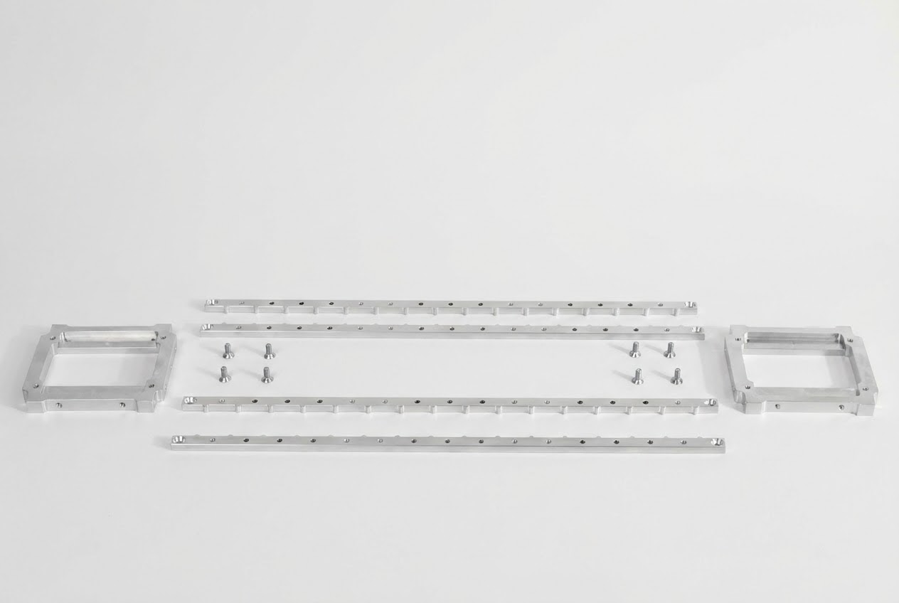
Required Materials:
- BAG A M5×12 Flat Head Socket Cap Screws (Qty: 8)
- Module Locators (Qty: 4)
- Aligner Brackets (Qty: 2)
- Loctite™ 248 thread locker
Required Tools:
- 3mm hex head (1/4" square drive for torque wrench or 1/4" quick release bit for torque driver)
- Torque wrench or driver set to 6 Nm (53 in-lbs)
- Flat work surface
Arrange & Assemble Bottom Rails
- Stand the Aligner Brackets upright as shown, ensuring the 80mm fan recesses are facing away from each other
- Place 2 Module Locator rails on top as shown
- Verify countersinks at each end face upward
- Confirm locating teeth for modules face inward towards each other
- Install four M5×12 FHSCS (BAG A) into each corner of the frame
- Apply a small amount of Loctite™ 248 to each fastener
- Tighten only enough for the screw head to be flush—do not torque yet
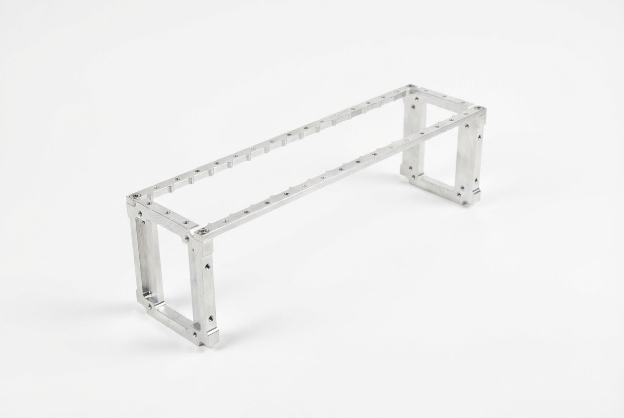
Arrange & Assemble Top Rails
- Flip the assembly over to access the opposite side
- Place 2 Module Locator rails on top as shown
- Verify countersinks at each end face upward
- Confirm locating teeth for modules face inward towards each other
- Install four M5×12 FHCS (BAG A) into each corner of the frame
- Apply a small amount of Loctite™ 248 to each fastener
- Do not tighten or torque these fasteners yet
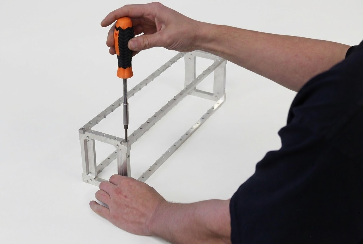
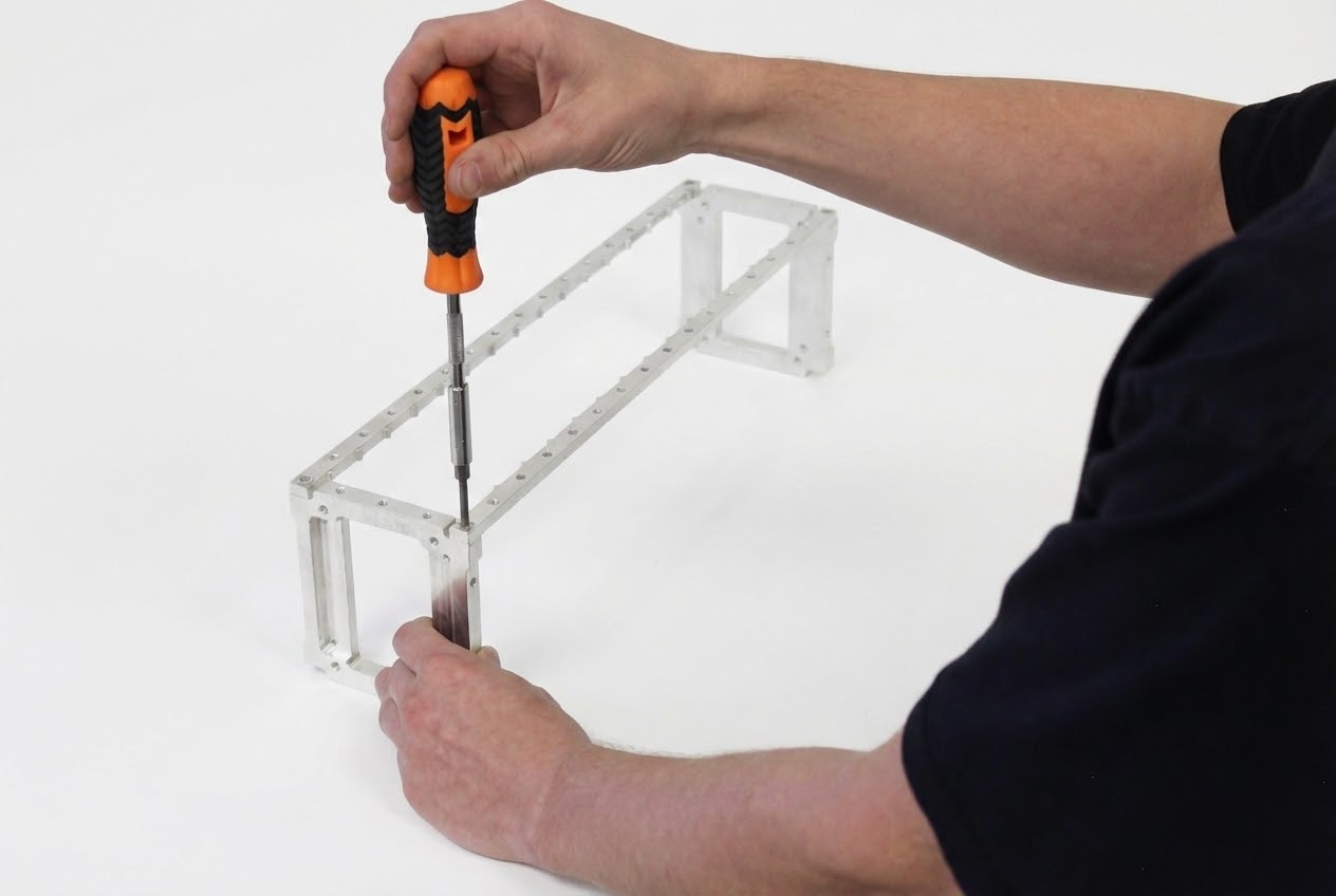
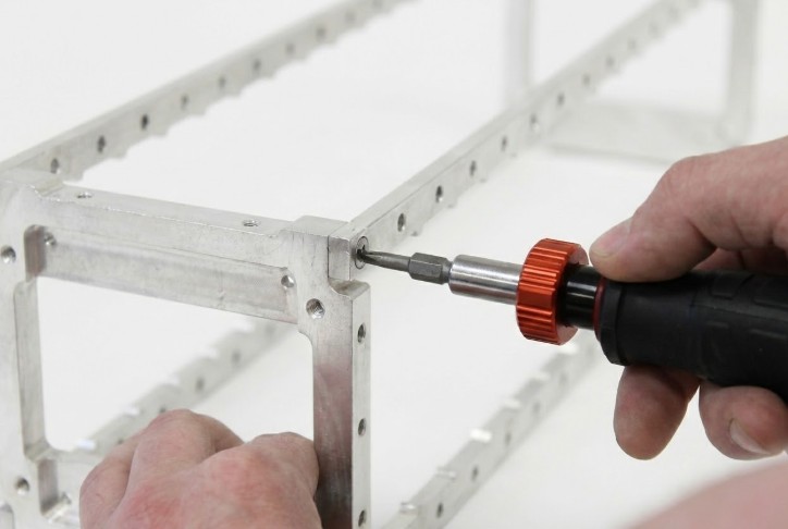
Square & Torque Frame Fasteners
- Set torque driver or torque wrench to 6 Nm (53 in-lbs)
- Rotate the assembly 90 degrees so it stands on edge
- Ensure all 4 corners of the frame rest flat on the work surface
- Apply downward pressure on the Aligner Bracket while torquing the fastener to 6 Nm
- Repeat for all 8 fasteners of the frame assembly
- Rotate and/or flip the assembly as necessary to access and torque all fasteners
Maximum: Do not exceed 60 in-lbs
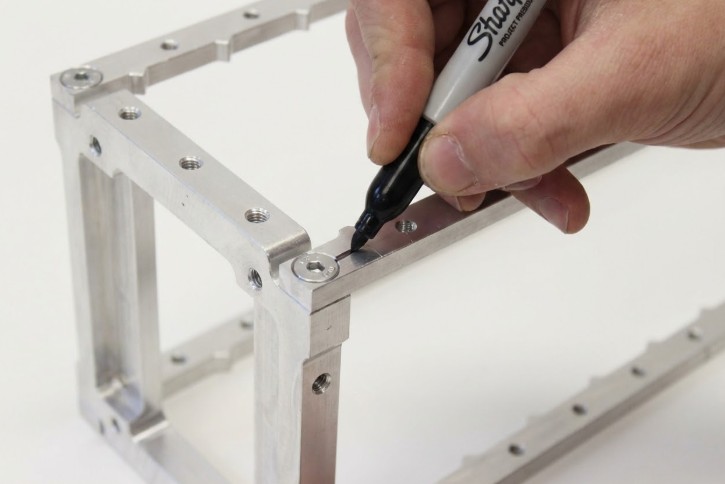
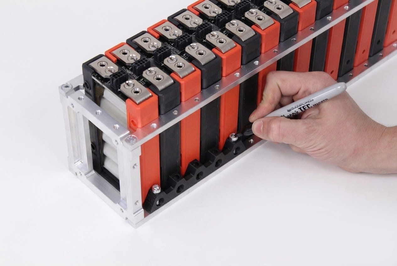
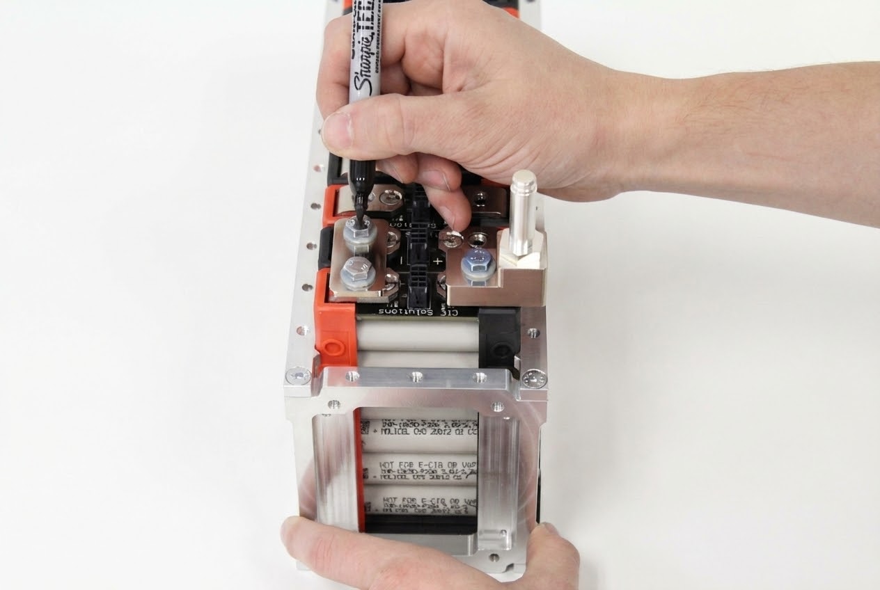
Mark Torqued Frame Fasteners
Quality control requires visual confirmation that all fasteners have been properly torqued with thread locker applied.
- Use a permanent marker or paint pen to apply a witness mark to each torqued fastener
- Mark should span from the fastener head to the surrounding material
- Apply torque marks only after a fastener has been torqued to specification with Loctite™ applied
- Verify all 8 frame fasteners are marked before proceeding
Torque Marking Best Practices
Torque marks serve as visual evidence of proper assembly. The mark should be clearly visible and span across the interface between the fastener and the component. If a fastener loosens, the mark will become misaligned, providing immediate visual indication of the issue.
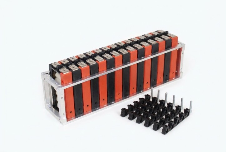
Section 2: Module Installation
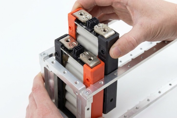
Populate Frame with Modules
⚡ POLARITY WARNING
Pay close attention to module orientation for correct polarity!
The red side of each module always indicates the cathode (positive) side. Verify module orientation matches your series/parallel configuration requirements before installation.
- Slide modules into the frame from above as shown
- Verify the red side (positive/cathode) is oriented correctly for your configuration
- Populate according to required series/parallel configuration
- Ensure modules seat fully into the locating teeth on the rails
Stage Materials for Module Retainers
Gather Required Parts & Tools:
- BAG B M5×25 SHCS (2 per Module Retainer)
- Module Retainers (quantity/part dependent on segment length)
- 4mm ball-tip hex bit (1/4" square drive or 1/4" quick release bit)
- Loctite™ 425 (cyanoacrylate-based, safe for plastics)
- Torque driver set to 36 in-lbs (~4 Nm)
⚠️ CRITICAL: Correct Thread Locker for Plastics
Loctite™ 248 (specified for previous steps) and other common anaerobic thread lockers are often harmful to plastics.
Use ONLY Loctite™ 425 for plastic parts!
Time-Sensitive Material
Loctite™ 425 is cyanoacrylate-based and therefore time sensitive. Plan your work in step 2.4 to torque each fastener to specification within 2 minutes of Loctite™ 425 application.
Reference: See Loctite™ 425 datasheet on Henkel website for additional information.
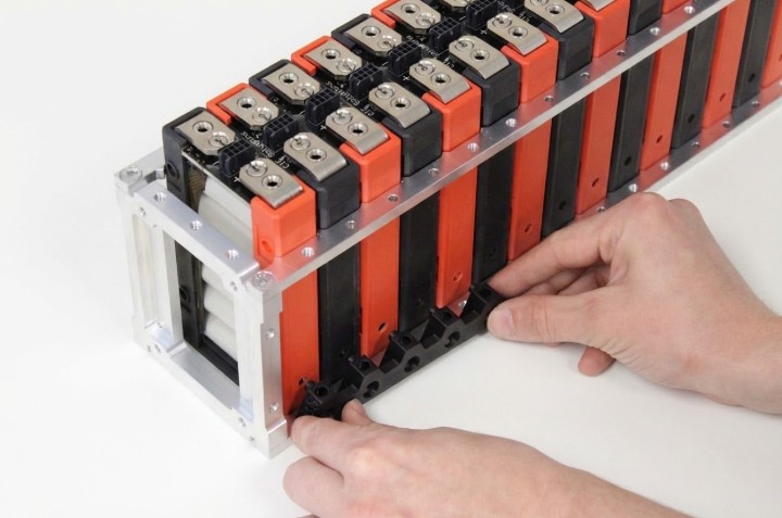
Mate Retainers with Modules
- Starting from one end, mate the module retainers by inserting the posts of the Module Retainer into the retention holes on the modules
- Ensure retainer posts are fully seated in the module retention holes
- Verify retainer alignment before installing fasteners
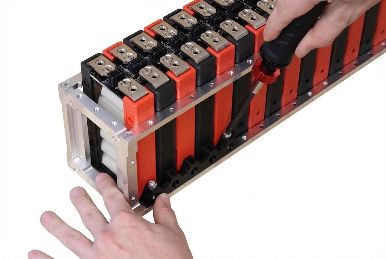
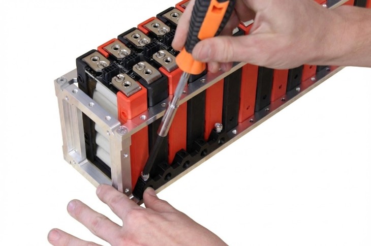
Install Fasteners For Module Retainers
Do NOT exceed 36 in-lbs or retainer damage may occur!
- Apply a small amount of Loctite™ 425 to each fastener before inserting
- Insert fasteners into the outermost vertical holes of each Module Retainer
- Thread both fasteners before torquing either one to ensure proper alignment
- Torque each fastener to 36 in-lbs (~4 Nm or 3 ft-lbs) within 2 minutes of Loctite™ application
- Apply torque mark to the head of each fastener after torquing
⏱️ TIME CRITICAL STEP
Loctite™ 425 begins curing immediately upon application. Torque each fastener to specification within 2 minutes of Loctite™ 425 application for optimal bond strength.
Complete Remaining Retainers
- Repeat steps 2.3 and 2.4 for the remaining retainers on the current side
- Rotate the assembly 180 degrees to access the opposite side
- Repeat steps 2.3 and 2.4 for all retainers on the second side
- Verify all retainers are installed and all fasteners are torque-marked
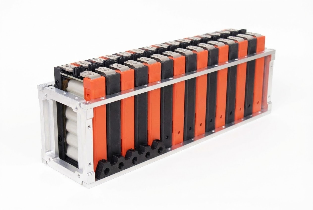
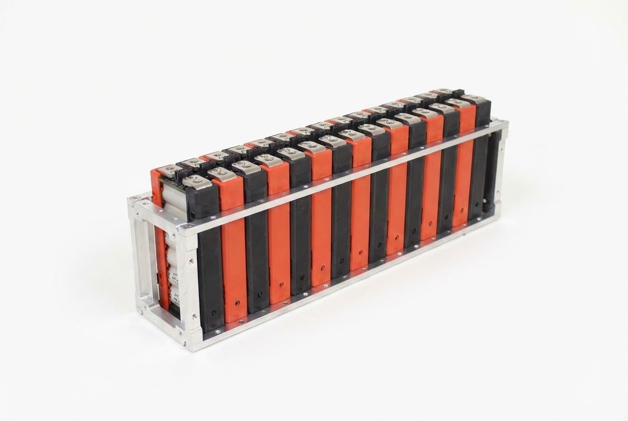
Section 2 Complete
At this point, all modules should be securely retained in the frame assembly with all fasteners properly torqued and marked. Verify complete installation before proceeding to electrical connections.
Section 3: Radsok® & Busbar Installation
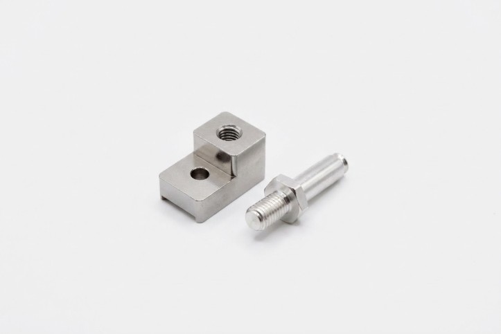
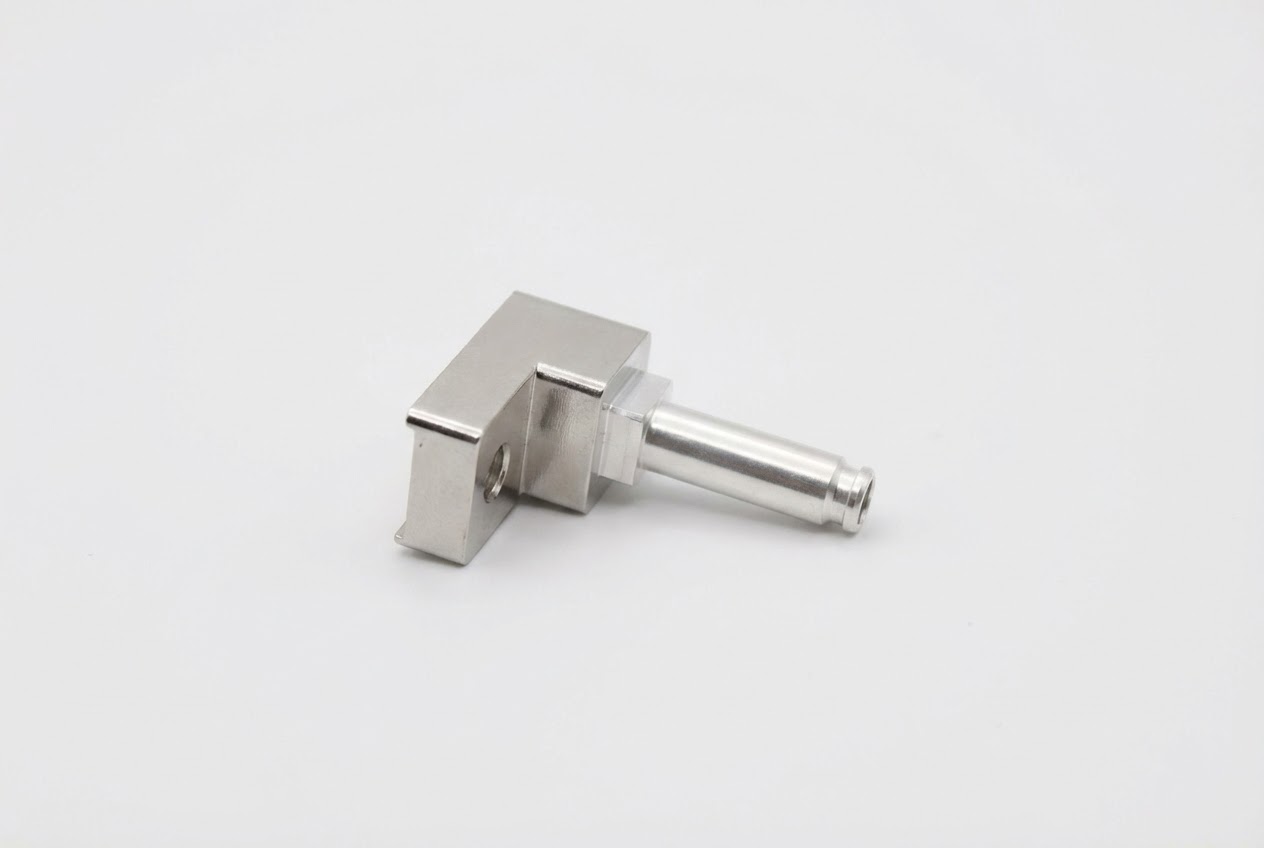
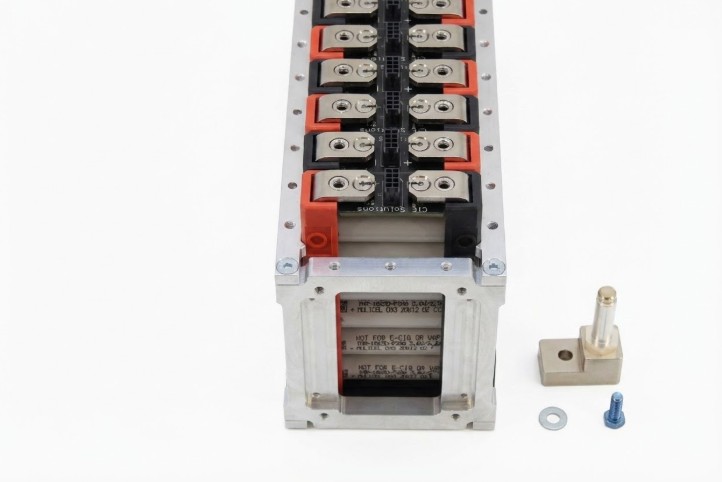
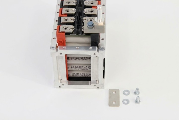
Prepare Radsok® Pin Mount Assembly
Required Parts:
- Radsok® Pin Mount (Qty: 2)
- Radsok® Pin (Qty: 2)
Required Materials & Tools:
- Loctite™ 248 thread locker
- 7/8" open end wrench
- 5/8" deep well socket
- Torque wrench set to 15 ft-lbs (20 Nm)
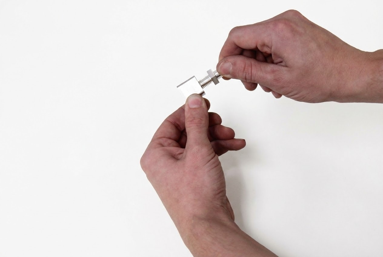
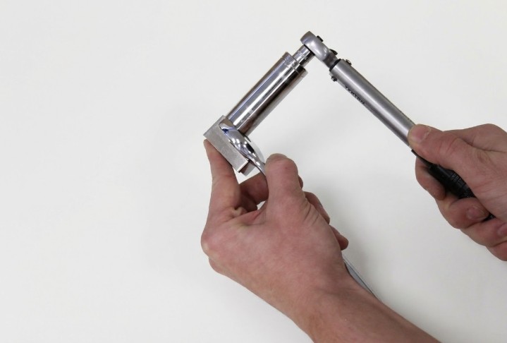
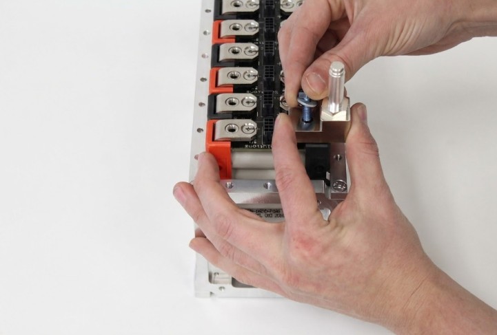
Assembly Steps:
- Apply a small amount of Loctite™ 248 to the threads of the Radsok® pin
- Thread the pin into the Radsok® Pin Mount as shown
- Hold the Pin Mount with the 7/8" wrench and torque the Radsok® Pin to 15 ft-lbs (~20 Nm) using the 5/8" deep well socket
- Repeat for the second Radsok® Pin Mount assembly
Materials & Tools – Radsok® Pin Mount Install
Gather the Following:
- BAG C M6×16 HHS (Qty: 2)
- BAG E M6 HD Safety Washer (Qty: 2)
- Completed Radsok® Pin Assemblies from previous step
- Loctite™ 248 thread locker
- 10mm socket
- Torque wrench set to 6 Nm (53 in-lbs)
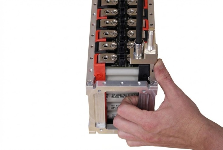
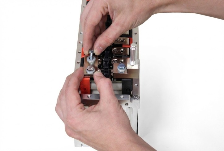
Install Radsok® Pin Assembly to Module
Installation Location
Radsok®s will be installed at the most positive and most negative positions of the assembly completed in Step 2.5 (the electrical terminals at opposite ends of the module string).
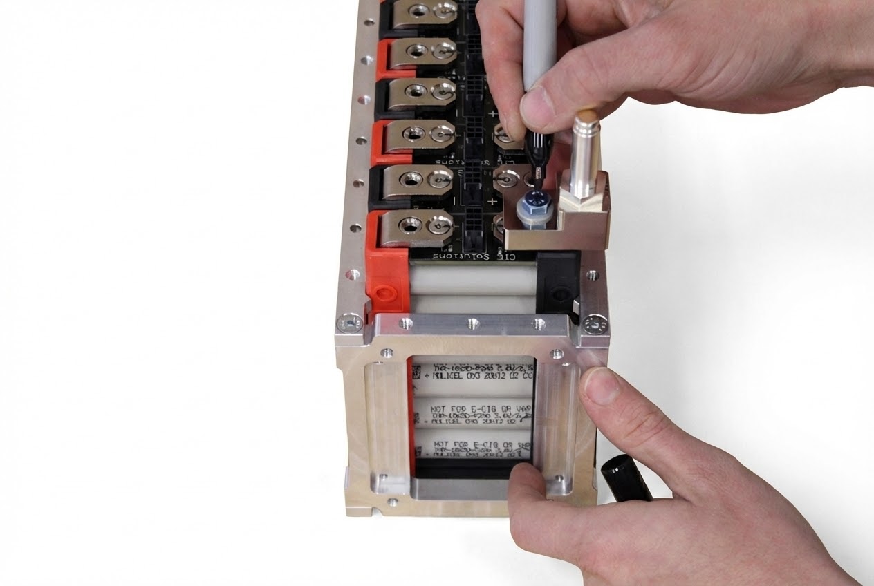
- Place the M6 washer (BAG E) on the M6×16 HHS (BAG C)
- CRITICAL: Ensure washer is oriented properly! The "cup" side should face the part, not the screw head
- Apply a small amount of Loctite™ 248 to the threads of the fastener
- Position the Radsok® Pin Assembly over the module terminal as shown
- Insert the hex head fastener through the open hole in the Radsok® Pin Assembly
- Thread fastener into the busbar connector of the module
- Torque the fastener to 53 in-lbs (6 Nm)
- Apply torque mark to the fastener
- Repeat for the opposite end of the assembly
Do NOT exceed 60 in-lbs or module damage may occur!
Materials & Tools – Busbar Install
⚡ HIGH VOLTAGE WARNING
Gloves recommended if bussing to high voltage!
30 VDC or greater is commonly considered high voltage. Each busbar installed in series increases the voltage of the assembly and thus increases risk during handling and pack assembly.
Safety Options:
- Option 1: Delay busbar installation until pack assembly is near complete, keeping active voltage as low as possible
- Option 2: Insulate all exposed electrical contacts with Kapton tape or equivalent once busbar installation is complete
Gather the Following:
- 2-Hole Busbar (per connection)
- BAG D M6×12 HHS (2 per busbar)
- BAG E M6 HD Safety Washer (2 per busbar)
- Loctite™ 248 thread locker
- 10mm socket
- Torque wrench set to 6 Nm (53 in-lbs)
Busbar Installation Procedure
- Place a washer (BAG E) on each fastener (BAG D)
- CRITICAL: Ensure washer orientation is correct! Cup side faces the part, not the fastener head
- Apply a small amount of Loctite™ 248 to the threads of each fastener
- Place the busbar over the desired position between modules
- Maintain firm hold on the busbar while inserting fasteners through both holes
- Thread both fasteners into the busbar connectors before releasing the busbar
- SAFETY: Threading both fasteners before release reduces the risk of busbar rotation causing a short circuit
- Torque each fastener to 53 in-lbs (6 Nm)
- Apply torque marks to both fasteners
- Continue with remaining busbars, working systematically from one end
Do NOT exceed 60 in-lbs or module damage will occur!
Installation Best Practice
Work systematically from one end of the assembly, ensuring no busbar positions are skipped. Verify series/parallel configuration matches your design requirements as you install each busbar.
Additional Busbar Connections
Continue installing busbars systematically along the module string, following the procedure established in Step 3.5.
- Work methodically from one end of the assembly
- Verify correct series/parallel configuration at each connection point
- Maintain consistent torque values and apply torque marks to all fasteners
- Double-check polarity before installing each busbar
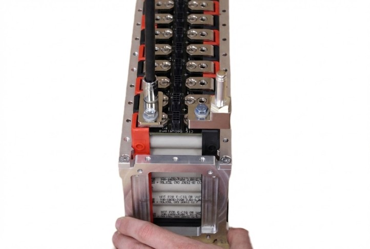
Verify Electrical Connections
Quality Control Check
Before proceeding to final assembly, verify all electrical connections are secure, properly torqued, and correctly configured for your application.
- Visually inspect all busbar connections for proper seating
- Verify all torque marks are present and properly applied
- Check that all spring lock washers are properly oriented
- Confirm series/parallel configuration matches design specifications
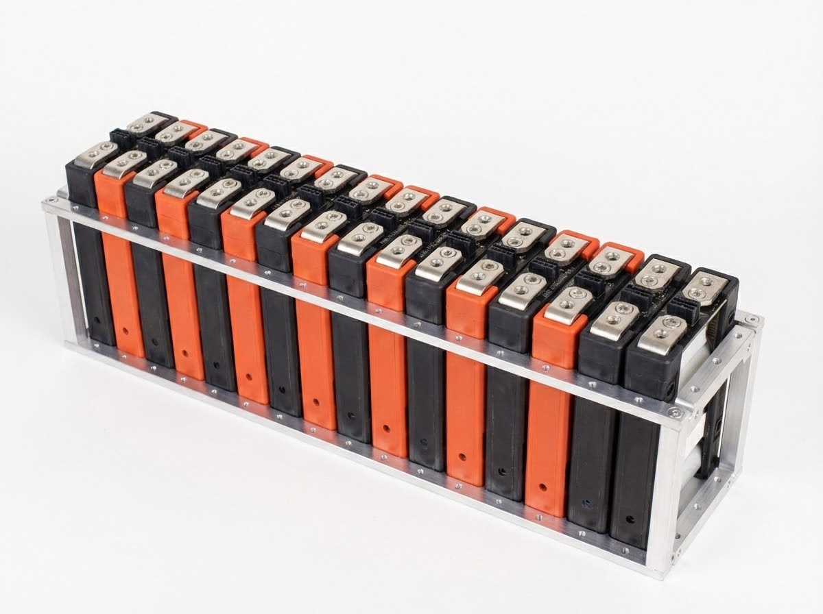
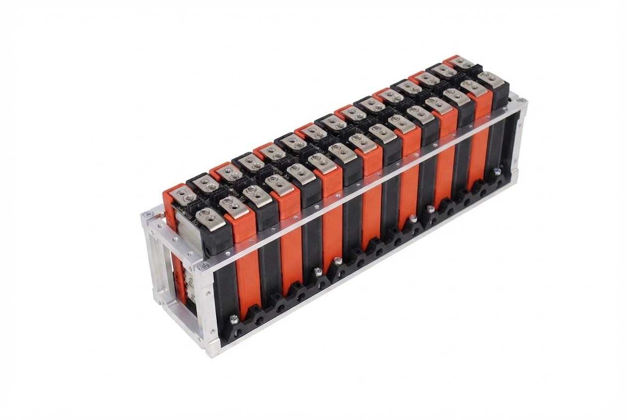
Section 3 Complete - Electrical Assembly
✅ Electrical Assembly Complete
All electrical connections are now installed and secured.
What Has Been Accomplished
- Radsok® Pin assemblies installed at both terminals
- All busbars installed with proper series/parallel configuration
- All electrical fasteners torqued to specification and marked
- Thermal management connections completed
Section 4: Mending Brace For Pack Assembly
Installation Timing
The Mending Brace should be applied after mounting the segments to the base plate during pack assembly. It is provided for additional structural strength when connecting multiple segments together.
Note: Mending Brace is shown applied on the workbench in these instructions for demonstration purposes only. Actual installation should occur during final pack assembly.
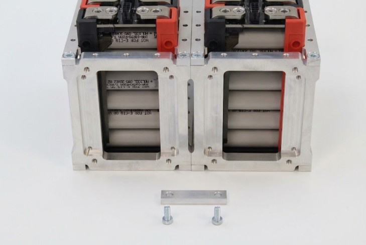
Mending Brace Installation Parts & Tools
Required Parts:
- Mending Brace
- BAG F M5×12 Low Profile SHCS (Qty: 2)
- Loctite™ 248 thread locker
Required Tools:
- 3mm hex head (1/4" square drive or 1/4" quick release bit)
- Torque wrench or driver set to 5 Nm (44-50 in-lbs)
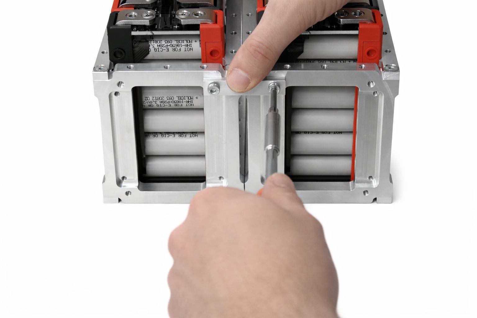
Mending Brace Installation
- Position adjacent segments on the base plate with appropriate spacing
- Place the Mending Brace over the mating holes on adjacent Aligner Brackets
- Apply a small amount of Loctite™ 248 to the threads of each fastener
- Thread one fastener through each hole in the Mending Brace into the M5 threaded holes of the Aligner Brackets
- Thread both fasteners before applying torque to either fastener
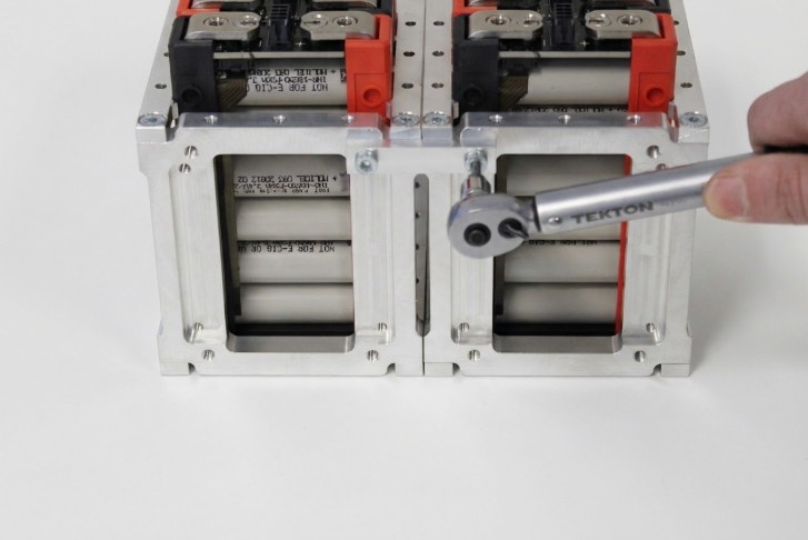
- Torque each fastener to 44 in-lbs (5 Nm)
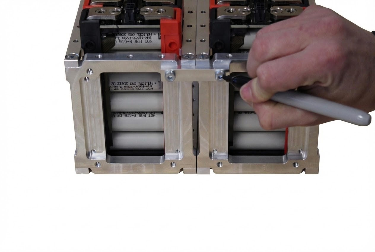
- Apply torque marks to both fasteners
- Repeat for additional mending braces as required by segment count
Do NOT exceed 50 in-lbs or damage may occur!
Verify Completed Installation
- Verify all fasteners are properly torqued and marked
- Check alignment of adjacent segments
- Ensure structural rigidity of mending brace connections
- Inspect for any gaps or misalignment between segments
Assembly Completion
✅ Assembly Complete
This concludes assembly instructions for the Lithium Block™ Bracket System.
All structural components are now properly assembled and secured.
Next Steps
- Verify all torque marks are present and aligned
- Inspect for any missed fasteners or incomplete steps
- Review mounting hole pattern dimensions provided with your purchase
- Proceed with pack-level assembly and integration
- Follow system-level installation procedures for your application
⚠️ Before Energizing System
- Verify all electrical connections are secure and properly torqued
- Confirm BMS is properly configured and communicating
- Test all protection circuits and safety interlocks
- Ensure thermal management system is operational
- Complete pre-commissioning checklist per system documentation
Additional Documentation
For complete system integration, refer to the following documentation:
- Lithium Block™ GEN2 Module Manual
- Battery Management System Integration Guide
- Mounting Hole Pattern Dimensions (included with purchase)
- System-Level Safety Procedures
- Commissioning and Testing Protocols