MonoLith™ Technical Overview
Technical Overview
A turnkey, modular lithium-ion battery system designed for vehicle prototype programs and development testing. Wire-bonded module arrays with integrated thermal management, BMS, and control architecture—engineered for rapid deployment and iteration.
The MonoLith™ platform is a pre-integrated battery pack system optimized for prototype vehicle programs and development testing. It delivers production-relevant architecture and safety systems while maintaining the flexibility needed for iterative development cycles.
Pre-validated system architecture eliminates 6-12 months of typical pack development time. Fully documented integration procedures enable faster vehicle bring-up.
24-cell building blocks in five series configurations (1s-6s) enable precise energy/voltage targeting. Scale from 10 kWh to 200+ kWh using standardized cooling arrays.
Multi-layer protection: cell-level CID, wire-bond redundancy with fuse-like behavior, pack-level fusing, and BMS monitoring/limits. Defense-in-depth approach for prototype environments.
CAN 2.0B interface provides complete visibility into pack health, limits, and diagnostics. DBC file and ICD included for seamless VCU integration.
Liquid or air cooling options with integrated thermal distribution. Operating range: -40°C to +60°C discharge, 0°C to +60°C charge.
Complete technical package includes: CAD models (STEP), electrical schematics, BMS configuration, CAN DBC, integration procedures, and test plans.
MonoLith™ is designed for prototype and development programs. This is not a production pack. The platform enables vehicle integration in parallel with your production battery development path. Typical program lifecycle: 2-5 years, decommissioned prior to production validation testing.
Comprehensive technical data for engineering teams and system integrators. Click any specification to expand detailed notes and integration considerations.
High-mix platform supporting wide energy range. Final installed energy depends on module variant selection, array count, enclosure choice, and duty cycle requirements. Use the online configurator for quick estimates; we generate configuration-specific datasheets on request.
Series configuration options for the 24-cell building block. Each variant provides different voltage/capacity trade-offs. Parallelization and pack topology (series/parallel arrangement) are selected per program based on system voltage and energy requirements.
Typical envelope supports 1–8 cooling arrays with 18 modules per array. Actual module count depends on control shelf configuration and enclosure selection. Each cooling array is an independently serviced thermal zone.
High energy density cylindrical cells (21700/18650 formats). Cell selection is program-specific based on power/energy/life requirements. All cells undergo incoming quality control and formation cycling before module assembly.
Storage range: -40°C to +85°C. Power derates and cold-soak heating protocols are program-specific per integration requirements. Thermal solution choice (air/liquid cooling) and enclosure selection affect operational temperature limits.
Module-level specific energy basis. System-level specific energy varies with enclosure mass, harnessing, mounting hardware, and cooling system selection. Typical system-level: 80-95 Wh/kg depending on configuration.
Ingress protection rating depends on enclosure selection. Module arrays are designed for sealed environments. Vibration and shock profiles are verified against program-specific test plans (e.g., MIL-STD-810, SAE J2380).
Overall pack dimensions vary with array count and enclosure design. Standard module dimensions: varies by series configuration. Full mechanical models (STEP files) provided for vehicle integration planning.
Defense-in-depth approach: Cell CID (current interrupt device) → Wire-bond redundancy with fuse-like behavior → Pack-level fusing → BMS monitoring and software limits. Each layer provides independent protection against fault propagation.
BMS supervises HVIL (high-voltage interlock loop), precharge sequencing, and contactor control. Publishes real-time limits (current, power, voltage) and health metrics on CAN bus. Vehicle Control Unit (VCU) commands loads within published limits. Clear authority partitioning for safety-critical functions.
Full telemetry, limits, and fault reporting via CAN 2.0B. DBC file provided with all signal definitions. ICD (Interface Control Document) specifies message IDs, update rates, and timing requirements. Message IDs and rates configurable within documented bounds for multi-pack systems.
Not a pre-certified pack. We supply the documentation package and test plans required to run certification on your final configuration. Test protocols aligned with UN 38.3 (transport) and UL 1973 (stationary energy storage) as applicable to program requirements.
Nominal system voltage determined by module series configuration and pack topology. Common configurations: 350-400V (light vehicles), 600-800V (heavy-duty). Min/max voltage limits provided in configuration-specific datasheet.
High-voltage connector selection based on current requirements and program preferences. Standard options include Amphenol HVP series and TE HVIL connectors. All connectors include integrated HVIL signaling for safety interlock verification.
BMS requires low-voltage auxiliary power for control and monitoring functions. Standard configurations support 12V or 24V vehicle systems. Power consumption: <10W idle, <50W active (including contactors and cooling pump/fans).
MonoLith™ delivers production-relevant architecture and safety systems while maintaining the flexibility required for iterative prototype development. Key engineering advantages for vehicle integration teams:
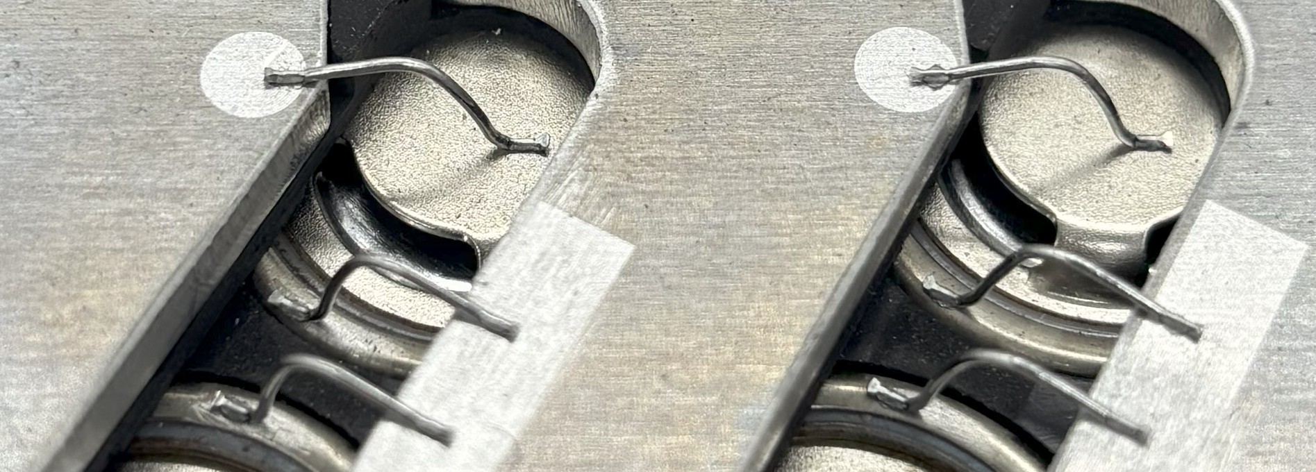
Ultrasonic wire bonding eliminates traditional busbar/tab welding failure modes. Benefits include:
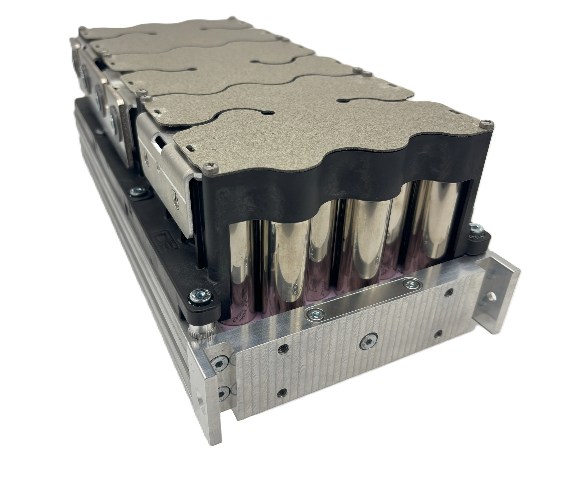
Module arrays ship as complete thermal zones with integrated cooling distribution:
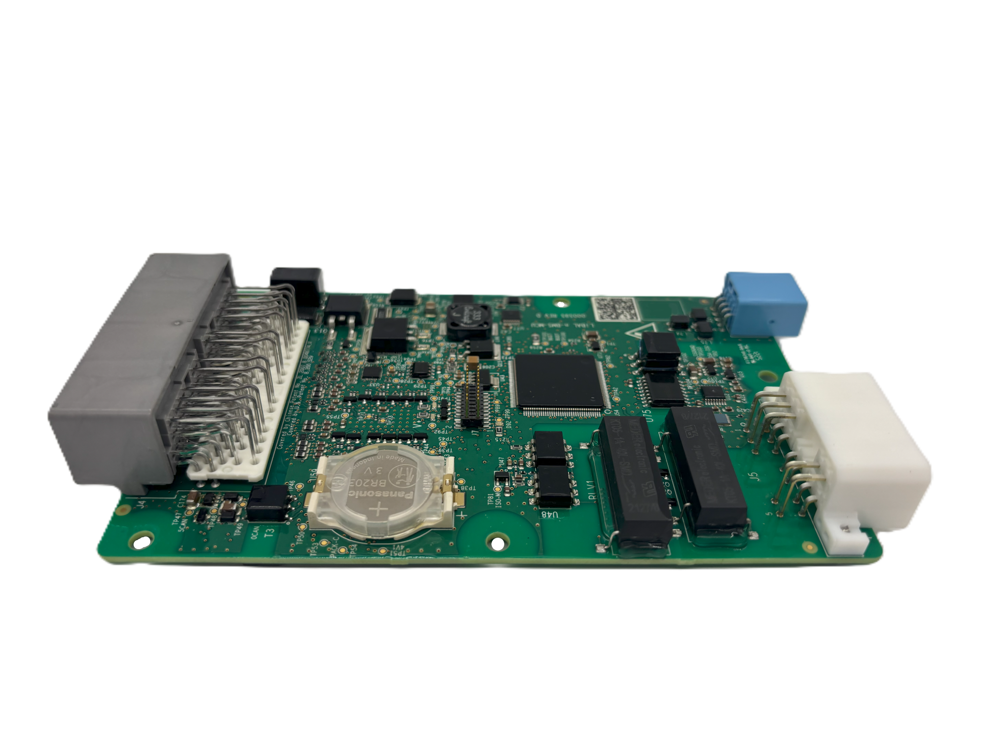
Battery Management System designed for prototype flexibility with production-grade functionality:
MonoLith™ BMS limits and protection thresholds are software-configurable to support iterative development. This is a prototype platform feature, not a production pack architecture. All limit changes must be documented and validated against cell specifications. Production packs require hardware-enforced safety limits.
MonoLith™ ships as a complete turnkey system with comprehensive documentation for vehicle integration. Typical deployment timeline: 4-8 weeks from order to first vehicle operation.
| Phase | Duration | Key Activities | Deliverables |
|---|---|---|---|
| Requirements Review | 1-2 weeks | Energy/voltage/power requirements, duty cycle analysis, packaging constraints, interfaces definition | Requirements document, preliminary configuration |
| Configuration & Design | 2-3 weeks | Module selection, array layout, enclosure design, connector selection, BMS configuration | CAD models, electrical schematics, ICD draft |
| Build & Test | 3-4 weeks | Module assembly, array integration, BMS programming, functional testing, acceptance testing | Tested pack assembly, test reports |
| Vehicle Integration | 1-2 weeks | Mechanical installation, electrical connections, HVIL verification, CAN commissioning, first charge | Commissioned vehicle, integration test data |
EVolve engineering provides direct integration support throughout vehicle commissioning. Includes: remote CAN troubleshooting, BMS parameter tuning, thermal management validation, and first-drive support. On-site commissioning assistance available for complex integrations.
Traditional prototype battery development requires 12-18 months and significant engineering resources. MonoLith™ delivers equivalent capability in 4-8 weeks by providing pre-integrated subsystems and proven architecture.
| Aspect | Traditional Approach | MonoLith™ Platform | Time Savings |
|---|---|---|---|
| Cell Selection | 6-12 months of testing and qualification | Pre-qualified cells with test data provided | 6-12 months |
| Module Design | 3-6 months design, prototype, validate | Production-proven wire-bonded modules | 3-6 months |
| BMS Development | 6-12 months hardware + software development | Validated BMS with configurable limits | 6-12 months |
| Thermal System | 3-6 months design, CFD analysis, testing | Integrated cooling with thermal models | 3-6 months |
| Safety Architecture | 6-9 months FMEA, testing, validation | Multi-layer safety system included | 6-9 months |
| Documentation | Basic specs, limited integration support | Complete technical package with ICD | Immediate |
| Total Timeline | 12-18 months | 4-8 weeks | 10-16 months |
Eliminate 12+ months of engineering labor (typical: 2-3 FTE). Avoid tooling and prototype iteration costs. Fixed pricing with no change orders for scope-compliant configurations.
Pre-validated architecture eliminates technical risk. Proven safety systems tested in demanding applications. Immediate access to replacement modules and service support.
Vehicle integration proceeds immediately while production pack development continues separately. Decouple vehicle and battery timelines for program schedule flexibility.
MonoLith™ platforms are deployed across aerospace, defense, industrial, and research applications where rapid prototype development and testing flexibility are critical.
Challenge: Rapid iteration required for flight test vehicle with changing power requirements during development.
Solution: MonoLith™ modular scaling enabled rapid configuration changes using same base module inventory. Completed 3 major configuration updates in 8 months.
Results: 3-month initial deployment, 225% cost savings vs custom approach, successful flight test program completion.
Challenge: Mission-critical application requiring rapid deployment and field serviceability with full documentation.
Solution: MonoLith™ pack platform with comprehensive diagnostics, documented installation procedures, and field-replaceable module arrays.
Results: Faster vehicle bring-up with documented install/test procedures, zero mission failures in 18-month field trial, exceeded MIL-STD requirements.
Challenge: AGV fleet needed standardized power across 5 different vehicle types with varying energy requirements.
Solution: Single MonoLith™ platform scaled from 25 kWh to 150 kWh across entire fleet using common module building blocks.
Results: Unified maintenance procedures, 50% reduction in spare parts inventory, 99.7% uptime achieved, simplified technician training.
Ready to accelerate your prototype program? Contact our engineering team to discuss your requirements and receive a detailed configuration proposal.
Speak directly with our technical team about your specific application requirements.
Phone: +1 (720) 414-5502
Email: [email protected]
Request a detailed quote with configuration-specific specifications and pricing.
Email: [email protected]
Form: Online Contact Form
Explore detailed product information and technical resources.
Step 1: Initial consultation (30-60 minutes) to understand energy/voltage/power requirements, duty cycle, packaging constraints, and timeline.
Step 2: Preliminary configuration proposal with CAD models, performance estimates, and budgetary pricing (3-5 business days).
Step 3: Requirements review and configuration refinement (1-2 iterations typical).
Step 4: Final quote with detailed specifications, pricing, and delivery timeline (typically 4-8 weeks from order).