Summary
Lithium-ion safety engineering begins from an uncomfortable premise: individual cells can fail, and no amount of quality control reduces that probability to zero. The discipline is therefore not the pursuit of a pack that cannot fail, but the management of what happens when a cell does. Industry practice, reflected in abuse-testing standards such as SAE J2464, is built on exactly this premise: characterize the response to off-normal conditions, expose the hazards, and design mitigations in layers so that no single layer is load-bearing for the whole outcome.
This paper walks the failure-management layers of the MonoLith platform, from prevention through detection, isolation, and containment. The through-line is a distinction that matters when evaluating any pack architecture: some safety layers are components that were added, and some are consequences of how the pack is arranged. Added components can be omitted, misconfigured, or value-engineered away. Geometric consequences come with the architecture.
The paper closes with an explicit statement of what the platform does not do, because a safety document that omits its own limits is not a safety document.
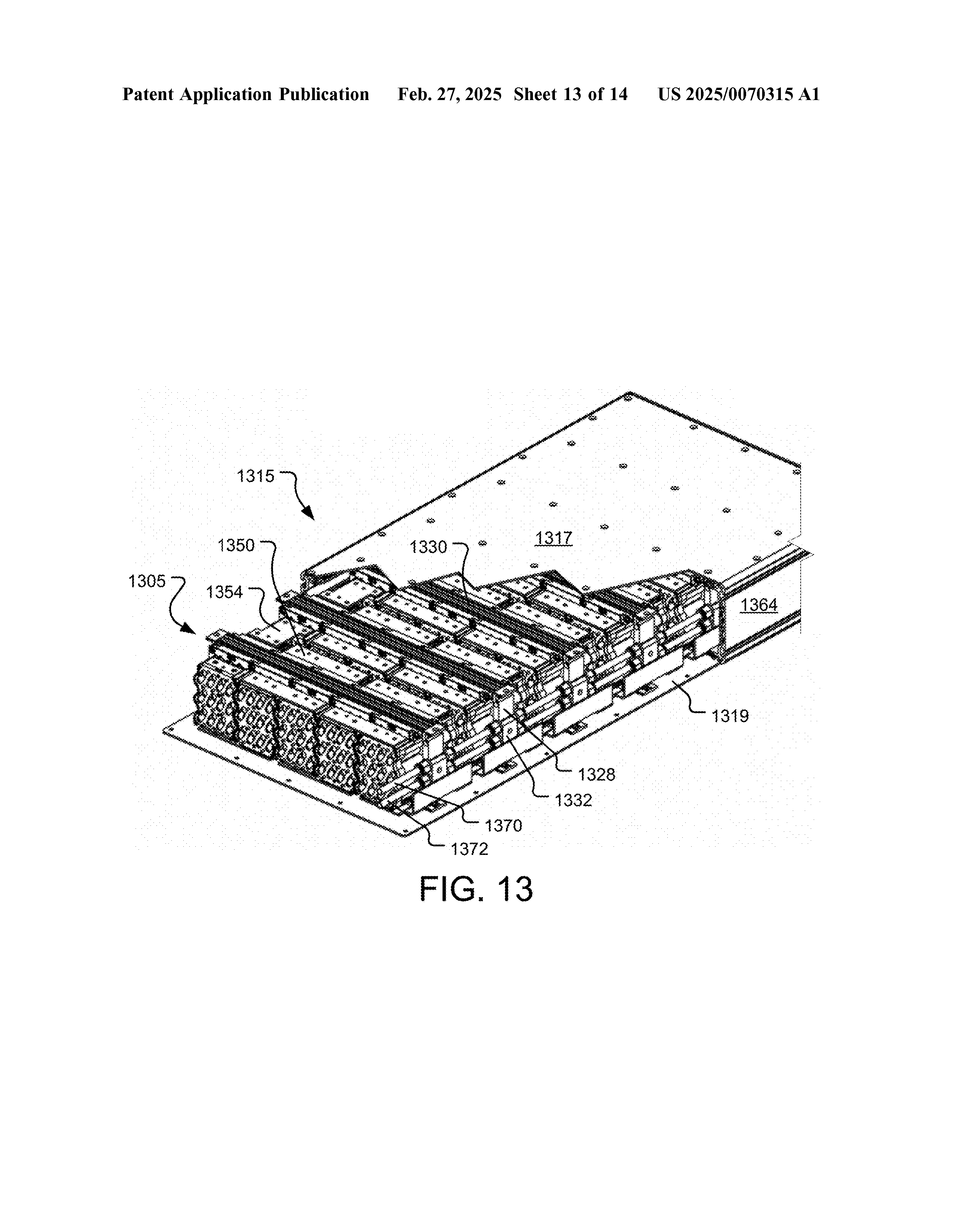
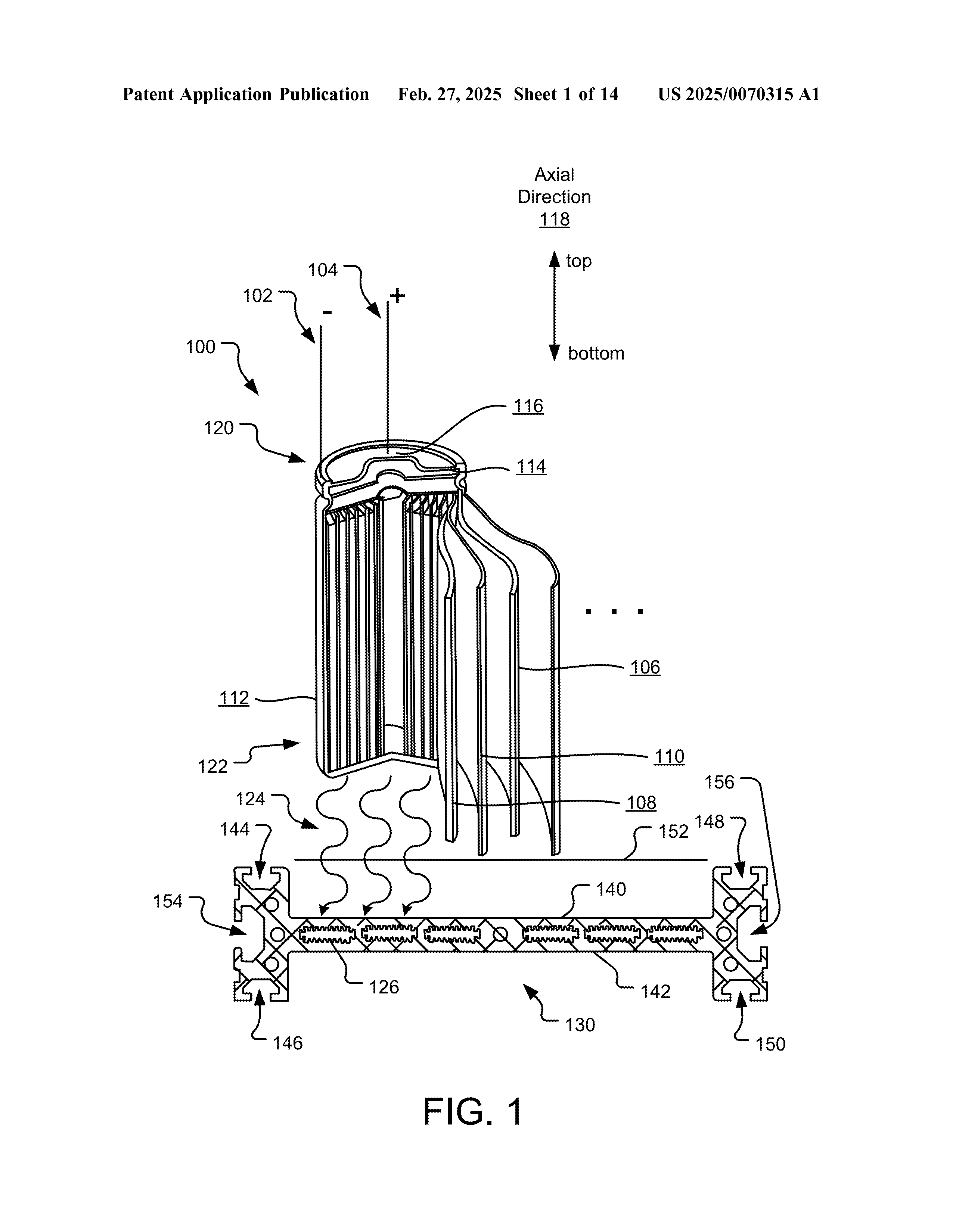
Figures depict the architecture as filed in August 2024 and may differ from current production configuration.
1.The Premise: Cells Fail, Packs Manage
A single cylindrical cell in thermal runaway releases its stored energy as heat and vented gas over seconds to minutes. In a pack containing hundreds or thousands of cells, the cell-level event is rarely the hazard that matters. The hazard that matters is propagation: whether the first cell's failure delivers enough energy to its neighbors to trigger theirs, converting a contained single-cell event into a cascading pack-level one.
Every design decision in this paper is ultimately aimed at one of four jobs:
Prevent
The conditions that precipitate cell failure, primarily thermal and electrical abuse.
Detect
A developing failure early enough to act.
Interrupt
The electrical and thermal paths that feed a failure or carry it outward.
Contain & Direct
The energy release of a failure that occurs anyway, so it exhausts without recruiting neighbors.
Storage and installation guidance for lithium systems, including SAE J3235, treats physical barriers and spacing as primary propagation controls for exactly this reason: distance and interruption of the energy path are what stop a cascade. The MonoLith architecture applies that logic inside the pack.
2.Prevention: The Thermal Argument, Briefly
The strongest failure prevention is unremarkable operation. Cell degradation and failure probability both rise with temperature and with temperature gradient, so a pack that holds its cells in a narrow, uniform thermal band is doing safety work continuously, invisibly, before any protective layer is invoked.
The MonoLith cooling architecture extracts heat through the cell base into a liquid-cooled thermal plate, along the axis of the cell where the jelly-roll construction conducts best. That argument is made fully in the companion paper in this series (WP-001) and is not repeated here. The point that belongs in a safety discussion is narrower: every cell in the pack sits on the same cooled structural surface, so thermal uniformity is a property of the mounting arrangement rather than of duct routing or airflow balance. The cooling that prevents abuse conditions is the same interface that holds the pack together.
3.Detection: Instrumentation as an Early-Warning Layer
The published application is explicit about the purpose of the platform's embedded instrumentation. Temperature sensors are mounted through the module structure, routed to quick-disconnect connectors, and monitored by the battery management system; the filing states directly that an unexpectedly high temperature at any sensor may indicate an imminent cell failure that could lead to combustion and adjacent cell failures. Detection is not telemetry for its own sake. It is the layer that buys time for every layer downstream.
In the platform's control model, the BMS monitors individual cell voltages and distributed temperatures, estimates state of charge and state of health, and publishes real-time operating limits on the CAN bus. The vehicle or system controller commands loads within those published limits, while the BMS retains authority over the safety-critical functions: high-voltage interlock supervision, precharge sequencing, and contactor control. The partition is deliberate. The system integrator owns performance; the BMS owns the envelope.
4.Interruption: Layers Between the Cell and the Fault
Between a healthy pack and a propagating failure sit several independent interruption mechanisms, at ascending scale.
At the Cell
Modern cylindrical cells carry an internal current interrupt device that opens the cell's own circuit under internal overpressure. This is the cell manufacturer's layer, and the pack architecture is designed not to defeat it: the cell top, where the interrupt and vent mechanisms live, is left unobstructed by the interconnection scheme.
At the Interconnect
Every cell terminal connects to its collector plate through ultrasonic wire bonds rather than welded tabs or busbars. The bond wires provide redundant current paths in normal operation, and under fault current a bond wire behaves like a fuse, opening and disconnecting an individual cell without mechanical intervention. A shorted cell is thereby electrically excised from its parallel group at the level of a single wire. Wire bonding also joins without applying weld heat to the cell terminal, which removes one manufacturing-induced abuse mode from the process itself.
At the Module
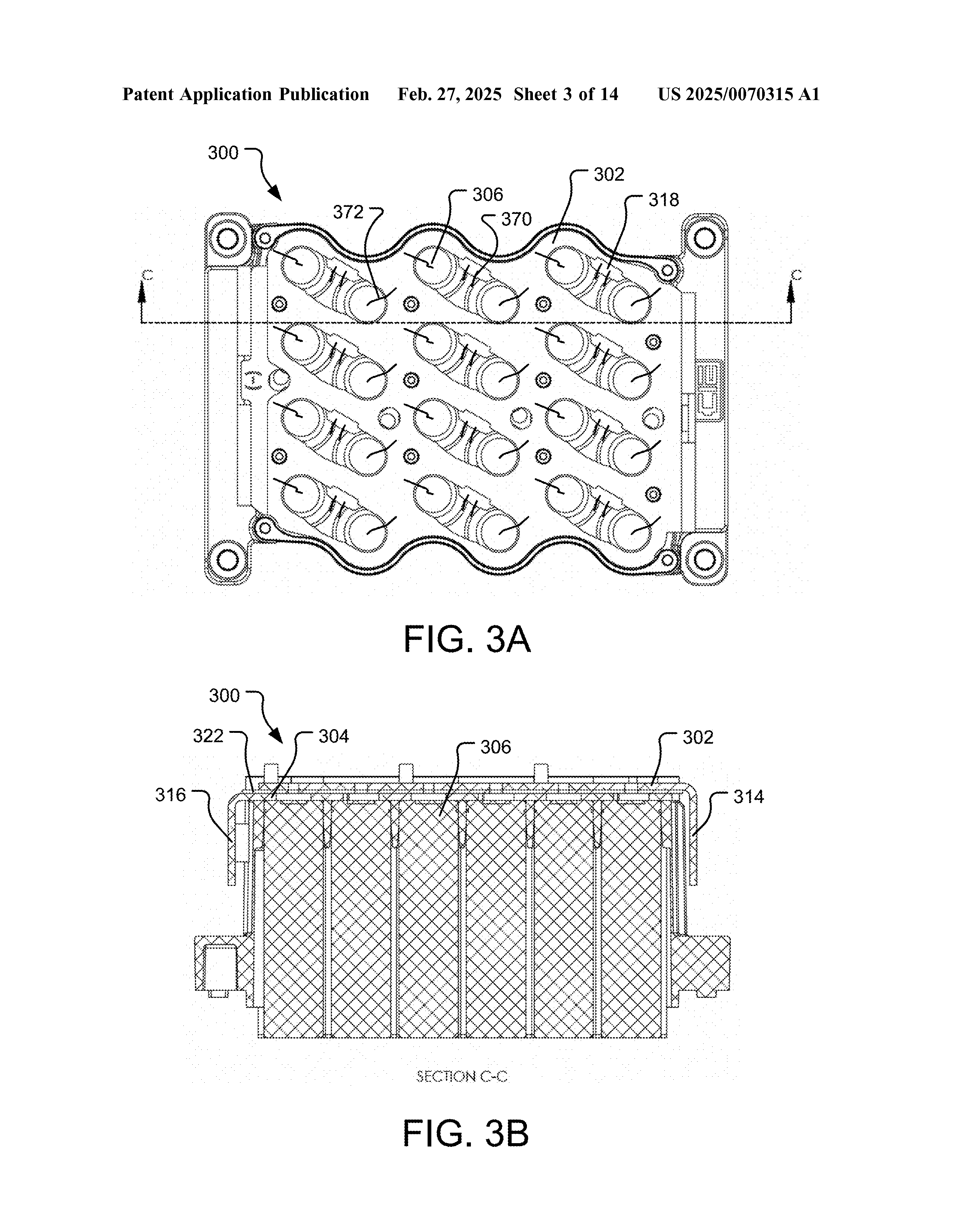
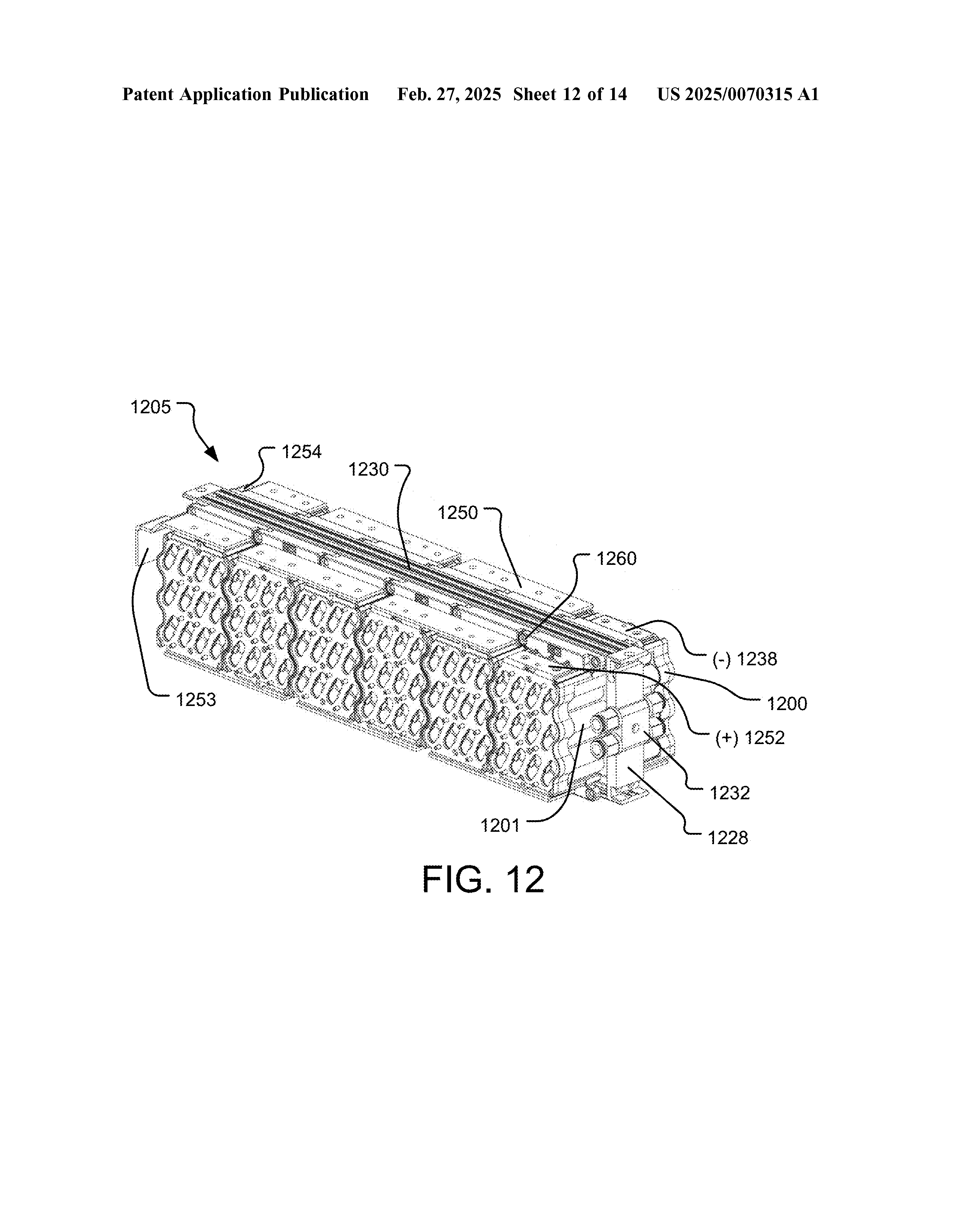
Cells sit in individual bores in an electrically insulating housing that mechanically secures each cell and prevents can-to-can contact between neighbors. Modules mounted in a row are separated from one another to prevent conductive contact between cells of adjacent modules.
At the Pack
Pack-level fusing and BMS-controlled contactors provide the conventional outer electrical layers, with the contactors under BMS authority as described above. A manual service disconnect at the pack exterior gives service personnel a physical break point, and the pack presents its high-voltage connections through an interlock-supervised interface.
5.Containment and Direction: The Geometric Layer
The layer most specific to this architecture is also the one that costs the least, because it is mostly arrangement.
Cylindrical cells vent through their top, where the terminals are. The MonoLith architecture already commits the cell top to electrical interconnection and the cell base to cooling, so every cell's vent path points in a known, consistent direction: away from the thermal plate, toward the outside of its sub-unit. Failure energy is not directed into the structural and cooling core of the pack.
That consistency creates one specific geometric problem, and the architecture answers it directly. When two sub-units are mounted facing each other within a pack, their vent directions oppose: a venting cell in one sub-unit discharges toward the cells of the other. Isolation plates placed between facing sub-units block that path, preventing a failing cell's vented discharge from impinging on the opposing sub-unit's cells. The filing states the purpose in plain terms: this reduces the possibility, or slows the occurrence, of a failed cell causing a chain reaction of further cell failures.
The phrasing deserves attention because it is honest. Reduces or slows, not prevents. Propagation control is probabilistic: barriers and spacing change the energy delivered to neighboring cells and the time available for detection and response. Slowing a cascade is itself a safety outcome, because the layers that act on time, detection, load shedding, and emergency response, all work better with more of it.
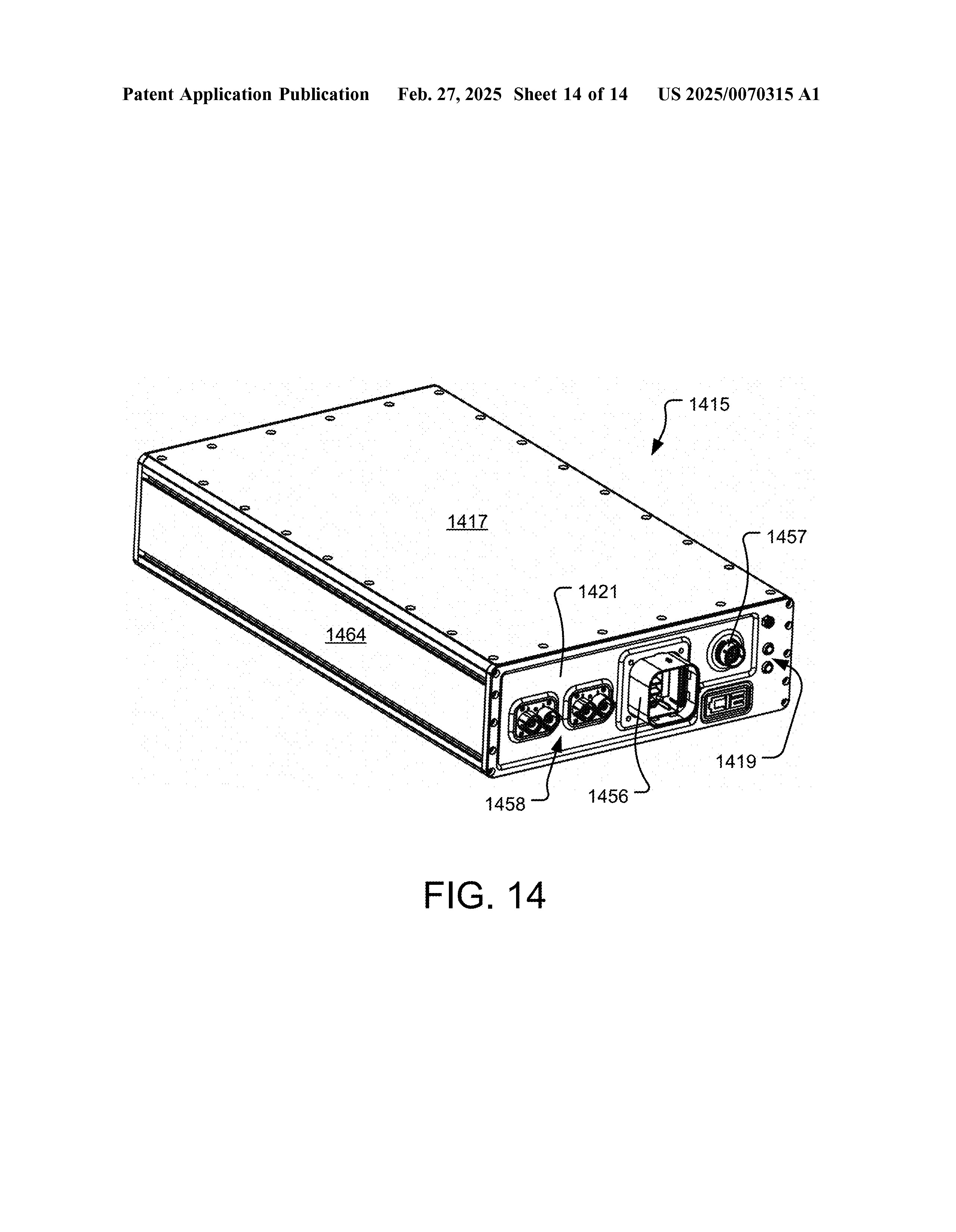
Structural panels and end caps then enclose the assembled sub-units, protecting against external contamination and contact, and the mounting rail system provides a continuous chassis ground path for the assembly.
6.Components Versus Consequences
Reading the layers together, a pattern emerges that is the actual thesis of this paper.
Some layers are components: the pack fuse, the contactors, the BMS, the isolation plates. Components are real protection, but they are also line items. They can be omitted from a variant, defeated by a configuration error, or removed by cost pressure, and their protection must be verified present in every build.
Other layers are consequences of the arrangement itself. Vent direction is consistent because the architecture already puts every cell top on the interconnect plane. Thermal uniformity exists because every cell shares the cooled structural surface. Cell excision under fault exists because the interconnect method is per-cell wires rather than shared tabs. Weld heat abuse is absent because the joining process does not use weld heat. These properties cannot be value-engineered out of a given build, because removing them means building a different architecture.
A layered safety system built partly from geometry is more durable than one built entirely from components, for the same reason a passive protection is preferred over an active one: fewer ways to be absent when needed.
7.What This Platform Does Not Do
Stated plainly, because the omissions define the integration work that remains with the program.
It Is Not a Certified Pack
The platform is designed with reference to industry safety and abuse-testing standards, and ships with the documentation and test plans needed to run certification on a final configuration, with protocols aligned to UN 38.3 for transport and UL 1973 for stationary storage as applicable. Certification is performed on the customer's final configuration, not inherited from the platform. Design reference is not conformity, and this paper claims none.
It Does Not Include Active Fire Suppression
The platform's containment layers are passive: orientation, isolation, separation, enclosure. Suppression, if the application requires it, is an integration-level system belonging to the vehicle, vessel, or installation, sized to the installation's hazard analysis and response concept. Programs in enclosed or occupied environments should treat this as an explicit integration requirement, not an assumed platform feature.
Protection Limits Are Software-Configurable
Configurable BMS thresholds exist so that development programs can adapt limits as requirements evolve, with changes documented and validated against cell specifications. Production systems require hardware-enforced limits, and a program transitioning from prototype to production should plan that transition rather than carry the development configuration forward.
Geometric Layers Depend on Correct Assembly
Vent direction management and isolation plate placement are properties of the specified arrangement. Field modifications that reorient sub-units or omit isolation plates remove the protections that arrangement provides.
8.Evaluating Any Pack, Including This One
The questions this paper implies are portable, and worth asking of any candidate architecture. Which safety layers are components and which are consequences? What happens to a single shorted cell, and what removes it from the circuit? Where does a venting cell's discharge go, and what is in that path? What does the detection layer see, and how much warning does it give? And which protections exist only in the datasheet's best configuration, versus in every configuration the platform can build?
An architecture that answers those questions structurally, before its component layers are counted, starts the bad day from a better position.
Patent Status
The architecture described in this paper is the subject of U.S. Patent Application No. 18/814,733, published as U.S. Patent Application Publication No. 2025/0070315 A1 on February 27, 2025, titled Modular Battery Pack with Liquid-Cooled Thermal Plates, and Canadian Patent Application No. 3,253,125. Both applications are pending. The applications were filed under the company's former name, CIE Solutions LLC.
References
- SAE J2464, Electric and Hybrid Electric Vehicle Rechargeable Energy Storage System (RESS) Safety and Abuse Testing, SAE International, 2021.
- SAE J3235, Lithium Battery Storage and Handling, SAE International, 2023.
- U.S. Patent Application Publication No. 2025/0070315 A1, Modular Battery Pack with Liquid-Cooled Thermal Plates, published February 27, 2025.
About EVolve Battery Systems
EVolve Battery Systems designs and manufactures custom lithium-ion energy storage systems in Boulder, Colorado. Founded in 2014 as a prototype engineering firm focused exclusively on bespoke battery systems, the company launched the MonoLith platform in 2025. Design, manufacturing, and R&D are performed in Boulder.
Engineering inquiries: +1 (720) 414-5502 | evolvebattery.us