Summary
Ask one question of any battery pack architecture: when a single cell develops an internal fault, what is the smallest unit the pack can electrically disconnect, and what disconnects it?
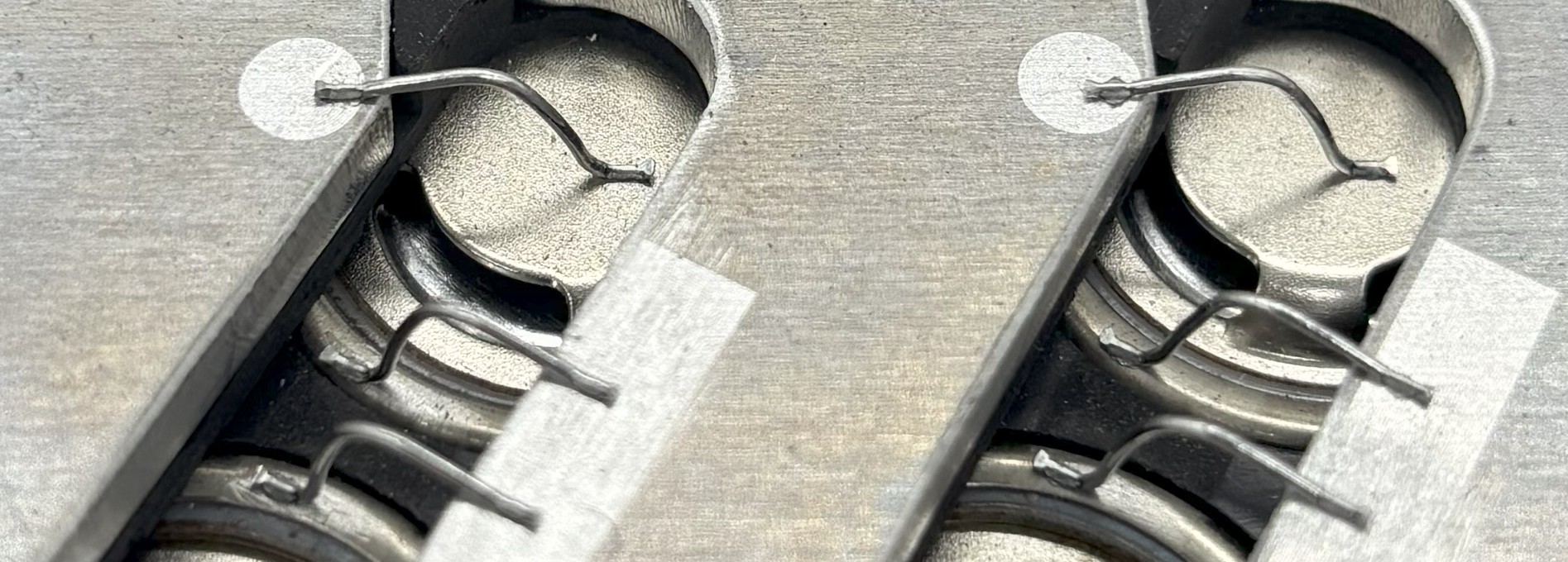
In a wire-bonded cylindrical pack, the answer is one cell, and the disconnecting element is the bond wire itself, which opens under fault current like a fuse. Combined with the current interrupt device built into small cylindrical cells, the architecture carries two independent, passive, per-cell disconnection mechanisms that require no sensing, no command, and no moving parts.
In a laser-welded prismatic pack, the answer is usually much larger. The building block is a large-format cell of fixed, substantial capacity, joined by welded busbars with no sacrificial element between cells, and protective devices live at the module or pack level. The architecture is not unsafe; it is certified and fielded at enormous scale. But its smallest unit of failure is bigger, and for a high-energy chemistry like NMC, the size of that unit is a first-order safety variable.
This paper describes the ultrasonic wire bonding process, the physics of the fusible-link behavior, the manufacturing consequences, and an honest comparison with welded prismatic construction, including what prismatic does better.
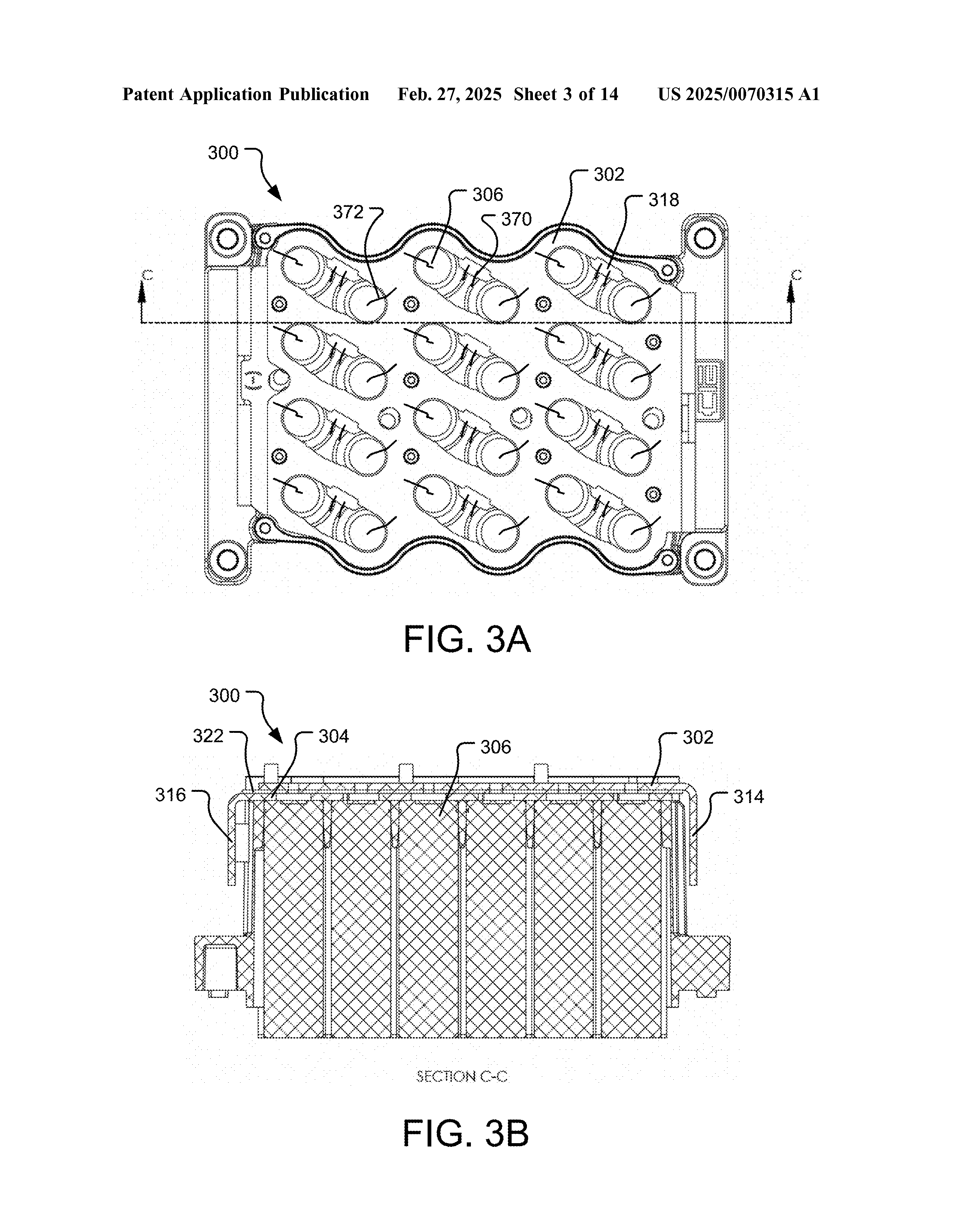
Figures depict the architecture as filed in August 2024 and may differ from current production configuration.
1.Granularity Is a Safety Variable
Thermal runaway management, as framed by abuse-testing practice such as SAE J2464, is about characterizing and limiting the response to a fault. Two numbers dominate that response: how much energy the faulted unit contains, and how much energy its neighbors can feed into it.
A 21700 NMC cell stores roughly 15 to 20 watt-hours. A large-format prismatic cell of the kind used in EV and stationary packs stores hundreds. When an internal short develops, the faulted unit's own energy sets the floor of the event, and the architecture sets the ceiling: whatever the surrounding parallel group can drive into the fault before something opens the circuit.
Granularity therefore acts twice. Fine-grained packs start from a smaller floor, because the faulted unit is small. And they can achieve a lower ceiling, if, and only if, the architecture places a disconnection element between each cell and its parallel group. Subdividing a pack into small cells without per-cell disconnection buys the smaller floor but not the lower ceiling: the parallel group still feeds the fault through solid metal.
Wire bonding is what makes the per-cell disconnection economical at cylindrical cell counts. That is its safety significance, and the rest of this paper is the mechanics of how.
2.The Cell's Own Layer: Why the CID Lives in Cylindrical Formats
Small cylindrical cells carry a current interrupt device in the cap assembly: a mechanical element that permanently opens the cell's internal circuit when internal pressure rises past a threshold, as it does during overcharge or early-stage internal failure. Alongside it, the scored vent in the cap gives gas a designed exit path. Both are cell-intrinsic: they ship inside every cell and work without any pack-level participation.
The CID is largely a small-format phenomenon, and the reason is current. A CID is a small conductive element in the main current path, and it must carry the cell's full operating current while remaining sensitive enough to open on demand. At the tens of amps a 21700 sees, that is a solved design. At the hundreds of amps a large prismatic cell delivers, a mechanical interrupter in the current path becomes impractical, which is why large-format cells rely on vents and external protection instead.
Choosing small cylindrical cells for an NMC pack is therefore not only a packaging decision. It is a decision to include a per-cell, cell-manufacturer-validated interruption layer that large-format construction cannot offer. The pack architecture's job is to not defeat it, which in the MonoLith design means leaving the cap end, where the CID and vent live, unobstructed by the interconnection scheme.
3.The Process: Joining Without Heat
Ultrasonic wire bonding is a solid-state joining process with half a century of heritage in semiconductor packaging and power electronics. A bond head presses a wire, typically heavy-gauge aluminum for battery interconnection, against the terminal surface and vibrates it ultrasonically under controlled force. The vibration scrubs away surface oxides and drives localized plastic deformation until the two metal surfaces share a metallurgical bond. The wire is then looped to the collector plate and bonded again at the far end.
Three properties of the process matter for battery assembly.
No Melting
The joint forms below the melting point of either material, so there is no heat-affected zone and no weld heat delivered into the cell cap. Every fusion welding process applied to a cell terminal deposits energy directly above the jelly roll, and process excursions there are a known abuse mode. Wire bonding removes that mode from the factory floor rather than controlling it.
Individually Verifiable
Bond quality is governed by force, ultrasonic power, and time, monitored per bond, and validated by destructive pull testing of process samples, following practice inherited from the semiconductor industry where the method has been qualified for decades.
Reworkable
A defective bond is removed and rebonded; a cell replacement during development means rebonding one cell’s wires, not cutting welded busbar. For a platform whose modules are expected to be serviced and iterated, the joining process and the service philosophy are the same decision.

4.The Fusible Link: Physics of a Wire That Knows When to Quit
A bond wire's current capacity is set by its diameter and length: Joule heating rises with the square of current, and past a threshold the wire melts and opens. This is the same physics that governs every fuse, and it means a properly sized bond wire is simultaneously a conductor and a passive overcurrent device.
In normal operation, each cell's current is spread across its bond wires with margin, and the platform's interconnection provides redundant paths, so the loss of a single wire shifts load to its partners rather than disconnecting the cell. Under fault, the situation inverts by design. A cell that develops a hard internal short becomes a sink for its entire parallel group, and the resulting current through that one cell's bond wires exceeds anything normal operation can produce. The wires open, and the faulted cell is excised from the circuit at the level of a single cell, passively, in milliseconds, with no dependence on detection or command.
The distinction between the two regimes is worth stating carefully, because it is what sizing the wire actually means: enough parallel capacity that operational current never threatens the wires, and little enough that fault current always does. Between those bounds, the interconnect protects itself.
Two boundaries on the claim, in the interest of precision. First, the fusible link answers hard external-path faults, where the parallel group drives current through the bond wires into the failed cell. A cell in full thermal runaway from internal causes is generating its event from its own stored energy, and no interconnect element can interrupt chemistry already in progress; that event belongs to the containment layers described in the companion safety paper (WP-003). Second, the opened wire disconnects the cell electrically, not thermally: an excised cell still exchanges heat with its surroundings, which is why per-cell disconnection complements, rather than replaces, thermal management and vent path control.
5.The Comparison, Honestly
The dominant alternative in high-volume packs is large-format prismatic cells joined by laser-welded busbars, and a fair account has to begin with what that construction does well.
Welded busbar joints are excellent conductors: large contact area, very low resistance, and mechanical robustness with no wire loops in the vibration environment. The joint count is small, hundreds rather than tens of thousands, which simplifies process control at automotive volume. Prismatic cells stack into rectangular volumes with high packing efficiency, and for LFP chemistry, whose thermal runaway is comparatively mild and which increasingly demonstrates non-propagation at the pack level, the coarse granularity is a reasonable match to the hazard. Certified, fielded, and proven at a scale no other construction approaches.
The trade is structural, not qualitative, and it has three parts.
The building block is fixed and large
Pack capacity quantizes in steps of the chosen cell’s amp-hours, and changing the block means requalifying a different cell. A cylindrical architecture adjusts capacity by parallel count in fine steps from a single qualified cell, which is a program-flexibility point developed in the companion structural paper (WP-002), but it is also a safety point: the unit of failure is chosen once, with the cell.
There is no per-cell sacrificial element
A welded busbar is designed never to open. Protection against a cell-level fault therefore lives at module or pack level, at a scale of many cells, and the energy between protection boundaries is correspondingly large. Some prismatic designs add cell-external fusing or rely on cell-internal features, but the welded joint itself contributes no interruption.
The chemistry raises the stakes
NMC stores more energy per liter than LFP and releases it more energetically in runaway, with lower onset temperatures and oxygen-contributing cathode decomposition. An architecture whose smallest isolable unit is a several-hundred-watt-hour NMC cell is accepting a large minimum event. The same architecture in LFP accepts a much smaller hazard for the same granularity. This is why the pairing matters in both directions: prismatic construction and LFP are a coherent match, and cylindrical wire-bonded construction and NMC are a coherent match. It is prismatic NMC where the granularity question presses hardest.
6.Costs of the Fine-Grained Approach
Symmetry requires the same honesty about wire bonding.
The joint count is enormous: every cell contributes multiple bonds, so a pack carries tens of thousands of individually formed joints, and the architecture's integrity rests on statistical process control at that scale. This is manageable, the semiconductor industry manages far more, but it demands bonding equipment, monitoring, and process discipline that fusion welding of a few hundred busbar joints does not.
Per-connection resistance is higher than a welded busbar's, which is part of why the approach suits high-parallel-count small cells, where each connection carries little current, rather than low-count high-current architectures. And the bond wires need mechanical protection in vibration environments, which the module and enclosure design must provide.
None of these costs is hidden, and none is novel: they are the known price of buying fault granularity, paid in manufacturing rather than in hazard.

7.The Stacked Result
For an NMC cylindrical pack built this way, a single cell's internal fault meets, in order and without any active system participating: the cell's own CID, positioned to act on the pressure rise of early failure; the fusible bond wires, sized to open under the parallel group's fault current; the cell housing and module separation that deny conductive paths to neighbors; and the vent orientation and isolation described in the companion safety paper. The active layers, sensing, limits, and contactor control, sit above all of it.
The design intent is that the expensive layers are never reached because the cheap, passive, per-cell layers acted first, at the scale of fifteen watt-hours instead of fifteen hundred. That is what fault granularity buys, and wire bonding is how it is paid for.
Patent Status
The interconnection architecture described in this paper is used in the MonoLith platform, which is the subject of U.S. Patent Application No. 18/814,733, published as U.S. Patent Application Publication No. 2025/0070315 A1 on February 27, 2025, titled Modular Battery Pack with Liquid-Cooled Thermal Plates, and Canadian Patent Application No. 3,253,125. Both applications are pending. The applications were filed under the company's former name, CIE Solutions LLC.
References
About EVolve Battery Systems
EVolve Battery Systems designs and manufactures custom lithium-ion energy storage systems in Boulder, Colorado. Founded in 2014 as a prototype engineering firm focused exclusively on bespoke battery systems, the company launched the MonoLith platform in 2025. Design, manufacturing, and R&D are performed in Boulder.
Engineering inquiries: +1 (720) 414-5502 | evolvebattery.us